Category Archives: General

Geotechpedia reached a 1000 links on Geotechnical Software Applications!

Since 2012 Geotechpedia’s database is continually growing of geotechnical engineering information, including links for free geotechnical paper and publications, links for geotechnical equipment, hardware and heavy duty machinery, links for geotechnical software applications etc.

Geotechpedia team is now pleased to announce that a thousand links on Geotechnical Software Applications have been registered!

Each software is presented in Geotechpedia with its title, publisher, price, a small description summary, perhaps a photo or a video, tags and of course the link. There is a variety of categories i.e. Geology Software, Geotechnical Design Software, Mining, Structural etc.

Geotechpedia’s database includes catalogued free downloadable Geotechnical Paper and Publications and links for Geotechnical Equipment and Hardware.

This makes Geotechpedia an essential tool for those interested in geotechnical engineering. Since our goal is to constantly improve our quality of service, feel free to contact us for any comments or suggestions at https://geotechpedia.com/About/Contact


Geosysta winning the Greece Challenge for ReTiMoS landslide monitor system, in the ESNC 2018!

Geosysta participated in the European Satellite Navigation Competition (ESNC) with the idea: “Real time monitoring of slopes and landslides with low cost GNSS receivers (ReTiMoS)” and was the Regional Winner of Greece.
Geosysta’s real time, cloud-based software Minefeed produces reliable storage, evaluation and alerts for slope stability monitoring based on records captured by topographic and geotechnical instruments. Geosysta has designed a system for real-time monitoring of slopes and landslides – ReTiMoS. This system can be used by the mining sector, highway operators and local authorities without significant experience in the field of slope stability to address the safely issue of upcoming or imminent landslides.
Geosysta’s idea was also one of the top 10 and she was invited to another very exclusive event as well, the E-GNSS Accelerator Bootcamp which took place on 04 Dec in Marseille, France.
The Awards Ceremony was held on 4th of December at the Palais du Pharo in the heart of Marseille, France, before an audience of about 600 invited guests.

The award received on behalf of the whole team, Mr. Chrysanthos Steiakakis, Civil and Mining Engineer, MSc, Co – Founder and CEO of Geosysta.

Special thanks goes to the Technical University of Crete and especially to Dr. Panagiotis Partsinevelos who is also an expert of the Galileo Masters, for their guidance, contribution and expertise.


Research Update on Geomembranes at Tailings Storage Facilities

This is a guest post by Sahar Pakzad, Marketing and Communications Coordinator at Klohn Crippen Berger Ltd.

Professor Kerry Rowe and Klohn Crippen Berger (KCB) alumnus Alan Chou of the GeoEngineering Centre at Queen’s University recently presented an update to KCB staff on the use of geomembranes at tailings storage facilities (TSFs). This update is a result of a multi-year research program, partly funded by KCB, involving fellow researcher Professor Richard Brachman, and KCB’s Dr. Prabeen Joshi and Harvey McLeod, P.Eng, P.Geo. The aim of the research is to quantify the amount of leakage through geomembranes at TSFs and the potential for the migration of tailings through holes in geomembranes into the surrounding environment.

Geomembranes are thin plastic sheets (usually less than 0.3 cm thick) installed as an impermeable barrier to limit the leakage of liquids or gases from containment facilities, such as municipal landfills, coal ash impoundments at power plants, heap leach pads and TSFs at mine sites. While installing geomembranes is standard practice for municipal and some industrial settings, only a small percentage of TSFs globally are lined by geomembranes, in part, because until now, there has been little research on their performance.

This research collaboration between Queen’s University and KCB is part of a longer-term research program at the university on how physical and chemical factors, including installation techniques, affect the performance and service life of geomembranes.

Geomembranes 101

Since the introduction of geomembranes in the mid-20th century, their properties and performance have significantly improved through advancements in polymer chemistry and installation techniques. Geomembranes are designed to resist degradation from exposure to UV rays, extreme temperatures and chemical reactions (including oxidation), and they must be strong and flexible to prevent stress cracking if they are folded or strained under significant loads.

Geomembranes are manufactured by combining a polymer resin with additives such as antioxidants, stabilizers, plasticizers, fillers, carbon-black, and lubricants (as a processing aid). These additives enhance the long-term performance of geomembranes by protecting the polyethylene from degradation (Ewais and Rowe 2014). There are several geomembrane types, including the most commonly-used high-density polyethylene (HDPE) and linear low-density polyethylene (LLDPE) geomembranes.

Not all geomembranes are the same, even from the same manufacturer; they differ in polymer additives and antioxidants, in colour, and in their physical properties such as stress crack resistance and service life. Geomembranes may also be custom blended to prevent reaction with containment materials.

Geomembranes are produced in long sheets, which are a few metres wide, and may be laid down and welded into panels on site (Figure 1a) or welded together in a factory before installation at site (i.e. fabricated geomembranes) (Figure 1b).

Figure 1a: Workers laying down a geomembrane
Figure 1b: Rolled fabricated geomembrane ready for installation
Figure 1b: Rolled fabricated geomembrane
ready for installation

Today, many jurisdictions mandate the use of geomembranes as part of a barrier system for specific applications. For example, in British Columbia, Canada, a landfill barrier system “shall be comprised of a primary High Density Polyethylene (HDPE) geomembrane liner and a secondary compacted clay liner or Geosynthetic Clay Liner (GCL)” (BC MOE 2016). Likewise, in Ontario, Canada, landfills must be lined by a “clayey liner with organic carbon content, in addition to an HDPE geomembrane liner, together with a leachate collection system” (Government of Ontario 2011). In the U.S., the Environmental Protection Agency requires that the bottom and sides of landfills be lined by “two feet of compacted clay soil” overlain by a geomembrane layer to “protect groundwater and the underlying soil from leachate releases” (USEPA 2017).

Leakage through Geomembranes

Geomembranes are not leak-proof as they degrade over time and may be punctured during installation, or by stones in the foundation material. They can also develop stress cracks at wrinkles or folds in the geomembrane following placement of the cover soil or tailings.

The team at the GeoEngineering Centre studied the performance of geomembranes under simulated field conditions typical for TSFs to quantify potential leakage. They found that leakage through holes up to 2 cm in diameter is less than 5 mL/s/km2, which is several orders of magnitude lower than leakage from unlined containment facilities (Joshi, P., pers. comm.). They also found “evidence of an increase in fines in the tailings and underliner in and around the hole” (Rowe et al. 2017).

Professor Rowe and his team performed puncture tests on geomembranes and found that a fine-grained foundation containing isolated stones may cause more geomembrane defects than a packed gravel foundation. They also found that stress cracks occur when there are wrinkles or folds in the geomembrane, when there is differential settlement of the foundation, and when the weight of cover soil or tailings drags the geomembrane down slope.

The colour of a geomembrane can be an important factor in its tendency to wrinkle. Even at moderate temperatures, a black geomembrane can become very hot, making it prone to wrinkling or folding, and in the process losing contact with its foundation. Researchers at the GeoEngineering Centre found that at the same air temperature, white reflective geomembranes can be 21–23°C cooler than black geomembranes, and that white geomembranes are less prone to wrinkling and developing stress cracks (Rentz et al. 2017).

The researchers concluded that damage to geomembranes can be minimized and the potential for leakage reduced by the appropriate selection of geomembranes, proper construction techniques (including adequate construction quality assurance), and by laying the geomembrane over a well-graded smooth foundation, preferably with a protective layer of sand or geotextile (Joshi et al. 2017). Geotextiles are permeable fabrics used for reinforcing slopes and filtering fine-grained material, while allowing water to drain.

Service Life of Geomembranes

The service life of a geomembrane is reached when it no longer adequately contains the material in the containment facility as designed. Its service life depends on its polymer type and additives, its exposure to UV rays, extreme temperatures and chemical reactions, and the potential for puncturing (predominantly by stress cracking).

The key to an effective barrier system is a protective layer between a drainage layer and the geomembrane. The protective layer not only reduces the risk of puncture in the short-term during installation and the initial placement of tailings, but helps to ensure an adequate geomembrane service life (Rowe 2016).

At TSFs, in addition to designing specialized geomembranes for resisting degradation, their degradation may also be reduced by a protective thick layer of tailings with consistently low ground temperatures (McLeod, H., pers. comm.).

A Critical Component of TSF Barrier Systems

By installing geomembranes at TSFs as part of a designed barrier system, mine operators can comply with local environmental regulations by significantly reducing the risk of leakage from TSFs into the environment and improving the recovery and recycling of water from tailings to other mine processing streams.

Ask us how we can help you with your tailings management needs.

For more readings on this topic, refer to the references below:

References

BC Ministry of Environment (BC MOE). 2016. “Landfill Criteria for Municipal Solid Waste.” Accessed June 26, 2017. http://www2.gov.bc.ca/assets/gov/environment/waste-management/garbage/landfill_criteria.pdf.

Ewais, A.M.R., and R.K. Rowe. 2014. “Degradation of 2.4 mm-HDPE geomembrane with high residual HP-OIT,” in 10th International Conference on Geosynthetics (10th ICG), Sept. 21-25, 2014. Berlin, Germany: International Geosynthetics Society.

Government of Ontario. 2011. “O. Reg. 232/98: Landfilling Sites.” Accessed July 24, 2017. https://www.ontario.ca/laws/regulation/980232#BK12.

Joshi, P., R. K. Rowe and R. W. I. Brachman. 2017. “Physical and Hydraulic Response of Geomembrane Wrinkles Underlying Saturated Fine Tailings”. Geosynthetics International. 24(1): 82-94.

Rentz, A.K., R.W.I. Brachman, W.A. Take and R.K. Rowe. 2017. “Comparison of Wrinkles in White and Black HDPE Geomembranes.” Journal of Geotechnical and Geoenvironmental Engineering. 143(8)

Rowe, R.K., P. Joshi, R.W.I. Brachman and H. McLeod. 2017. “Leakage through Holes in Geomembranes below Saturated Tailings.” Journal of Geotechnical and Geoenvironmental Engineering. 143(2)

Rowe, R.K. 2016. “Recent Insights regarding the Design and Construction of Modern MSW Landfills,” in EurAsia 2016 Waste Management Symposium, May 2-4, 2016. Istanbul, Turkey.

United States Environmental Protection Agency (USEPA). 2017. “Municipal Solid Waste Landfills.” Accessed June 21, 2017. https://www.epa.gov/landfills/municipal-solid-waste-landfills.

Guest Author: Ms. Sahar Pakzad, Marketing and Communications Coordinator at Klohn Crippen Berger Ltd.

Acknowledgement: Geotechpedia team would like to thank Ms. Sahar Pakzad, Marketing and Communications Coordinator at KCB Ltd, for sharing this post through Geotechpedia.

Disclaimer: Any views or opinions represented in this post are personal and belong solely to the author and all content provided is for informational purposes only. Geotechpedia makes no representations as to the accuracy or completeness of any information on this post or found by following any link on this post.


New era in site investigation data access

Our industry is a bit behind when it comes to new technologies, maybe it is because the scientific progress is moving slowly or not even significantly changing with time. For instance, we’re all still using Terzaghi’s early 1940’s one dimensional consolidation theory or the SPT to conduct our soil investigation. SPT was standardized between 1920 – 1930 and is still in practice today with minor modifications.

We need to explore new technologies in every part of our profession, from site reconnaissance with the use of satellite imagery or drones, to databases for site investigation and monitoring. We need to accept that technology is evolving rapidly and we should adjust and adopt, we need to go forward!

We still prepare site investigation reports in a static manner, we may use software to prepare them but in the end the reports and information they include is limited, without online cross references or procedures to easily update them with new or additional data. Maybe it is time to change?

Wouldn’t it be much easier if we could store our site investigation data electronically even from the field?

Wouldn’t be much more efficient if we could correlate different data or data from different locations or from different tests with a click of a button?

Why should we still be buried in thick reports, long sheets of borehole data, difficult to find or correlate and in the end to evaluate them? We are living in the google search era, we are used to type one word or one phrase and expect to have results in a few milliseconds. We should go forward!

It is time that we utilize new and available technology, utilize the power of easily accessed databases, the power of the cloud, being able to have access of our data from anywhere, from our laptop, from our tablet, even from our smartphone.

We need to be able to easily find in our data what we are looking for with a simple search box, just type a drilling name, or view in google maps our investigation area and have a quick look of the locations of our drillings in relations with structures, landforms etc. We need to press one button or tap our finger at the screen and access the information we are looking for. We need to be able to represent investigation data in different formats, for different people and different disciplines. Geologists may want to see information that engineers think is useless. Hydrogeologists may want to view a vast number of water chemical analysis next to the geological description of the ground, this is something that a geotechnical engineer would not appreciate much, he would prefer to see his laboratory index and strength tests. The mining reserve engineer would like to see his ore and mineral percentages. We don’t need to prepare different printed reports or different borehole logs for different disciplines any more.

We can now centrally store all our investigation data and then very easily select what we need to correlate with what or what type of information we want to see next to other information. We can do it from our tablet or smart phone.

We can be in a meeting and just tap in our smart phone the drilling we want and see any information we have stored in it in a very easy way. This technology is here and we should consider how it will increase our productivity and efficiency.

Evenmore, maybe very useful information could come out when you see different data placed together, which is very hard with printed reports. The geotechnical engineer gets his own format, the hydrogeologist his, this can stop today. Technology is here and we can easily adapt.

Geotechnical Risk Management

In our first ever post in Geotechpedia’s blog we tried to answer the most common question among professionals in the Geotechnical engineering industry “Geotechnical Investigation data, always not enough?”. In the specific post, it has been mentioned that “some of us proudly state “I saved so much by reducing the geotechnical investigation” but all this immediately changes when something goes wrong”. We are all aware of how limited or inadequate Geotechnical Investigation (GI) can affect both a project’s schedule and budget. In the following lines, we are trying to quantify these effects, provide guidance on how to easily create a risk scoring matrix and attributed risks, typical geotechnical risks and related mitigation measures.

Cost and time effect

Back in 1748 Benjamin Franklin stated “Time is money” in his “Advice to a Young Tradesman”. This quote finds application in all business sectors and the engineering one couldn’t stand out as an exception. In every project, delays are translated into cost and as such we are going to examine the estimated cost effects of delays deriving from inadequate Geotechnical Investigation on a project’s total construction budget. The most common chart when discussing the risk management in geotechnical engineering is presented below (Figure 1). It is obvious that for low values (1% approximately) of Geotechnical Investigation cost / tender cost (adjusted values), the total increase in construction cost may vary between 2% and 98% with an average value of 15-25%. When the Geotechnical investigation budget is slightly increased (adjusted Geotechnical Investigation cost / construction tender cost values between 2 and 4%) then the total increase in the construction cost drops to a typical range of 2% to 25% with an average value of 5-10%; meaning that an increase of 1-2% on the construction tender cost for additional Geotechnical Investigation signalizes a significant drop of approximately 25 to 50% (absolute values) in the total construction cost.

Figure 1: Total increase in construction cost related to adjusted Geotechnical Investigation cost / construction tender cost (source: UK Highways Agency projects (1994))

 Typical Risk Scoring Matrix

During the tendering procedure of a project, a risk assessment needs to be undertaken in order to evaluate the geotechnical risks at an early stage and propose mitigation measures. The following table (Table 1) presents a typical and simple scoring matrix that can be used in this kind of assessments and Table 2 details the specific risks associated with geotechnical works and categorizes them into probability of occurrence and cost/time impact.

The purpose of the following matrix is to help rank the key risks on site.

Table 1 Risk scoring matrix


Scores of 1-5 are allocated to the probability and impact in order to quantify and rate the risk rating. The risk scoring matrix should be used in conjunction with the priority action table detailed below (Table 2).

Table 2 Priority action table


Typical Geotechnical Hazards and recommended mitigation measures

Successful implementation of the suggested mitigation measures will assist with managing and reducing known risks to acceptable levels.

Table 3 below presents typical risks/hazards, related impact on construction budget and proposed mitigation measures.

Table 3 Risk/hazard assessment and proposed mitigation measures

In general, Geotechnical Risk Management gains supporters through the Projects Manager’s community since experience has proved that inadequate or incomplete Geotechnical Investigation during the tendering stage can have a severe impact on a project’s schedule and overall cost. Moreover, managing geotechnical risks also helps to increase safety levels in siteworks.

Conclusions

We need to keep in mind that geotechnical risk cannot be avoided and ignored but it can be managed and mitigated.

Taking all the above into consideration it is recommended that a detailed Geotechnical Investigation program is proposed at early stages of each project, following an in-depth desk study of all available information and site walk-over surveys.

It must be highlighted that the above post and its recommendations are to be read in conjunction with site specific available information and with critical thinking. In all cases, the Designer should set strict guidance for adequate Geotechnical Investigation in line with project specifications and international standards.

Useful References

[1] BS5930:1999, British Standard Code of practice for Site Investigations

[2] EuroCode 7 – IS EN 1997-2:1997 (Part 2, Annex B3)

[3] Clayton, C.R.I. (2001) Managing geotechnical risk, Thomas Telford.


Measuring Permeability and Fluid Storage in the Ground

This is a guest post by Mr. Ian Gray, Managing Director of Sigra Pty Ltd.

Towards a technology for shallow testing in civil projects

Permeability chart

We have found that the equipment and methodology being employed for permeability testing in shallow wells to be, if not inadequate, at the very least misapplied.

We propose a cross-disciplinary approach — involving new technology and the application thereof — to meet the requirements of shallow permeability testing.

Permeability measurement is important because it is part of the prediction of the rate of fluid inflows, fluid loss, or how fluid pressures vary in the ground. For instance, a civil engineer will want to know whether ground water will pose a problem for whatever structure they are designing and building.

Apart from the rare instance of a steady state situation, all formation pressures change with time, and therefore the ability of the ground to store fluid matters.

To sensibly conduct any measurement one must first understand the geology.

While it’s acceptable to gain such an understanding from either borehole samples, borehole geophysics, or broad area methods like seismic or resistivity, we feel it’s much more useful to employ all these methods together.

Each engineering discipline has developed its own way of measuring permeability and storage behaviour, and we do feel that these practices have often proved inadequate, specifically in reference to civil projects, and could be improved with some understanding of the process and the use of suitable technology.

Let us examine these practices.

Methods and issues encountered by hydrogeologists and petroleum engineers.

Hydrogeologist

The hydrogeologist who requires groundwater will choose to drill a well or wells into a suitable aquifer, and will pump from this to determine the production rate versus pressure (head) depletion in the well.

They will then observe pressure (head) changes in adjacent wells, so that the storage behaviour of the aquifer may be deduced.

These other wells are of course an extra cost to any project. However, they are the only way in which the storage behaviour in the ground may be properly determined.

Long term pumping tests of wells and the response in adjacent wells is a very good way to determine aquifer characteristics. Hydrogeologists will interpret their measurements in terms of hydraulic conductivity, which is a combination of absolute permeability of the ground and the viscosity of water.

They will describe the storage behaviour in terms of yield of fluid per unit area per unit fluid head change. The storage term used for a confined aquifer is storativity, and for the unconfined case, specific yield.

Petroleum Engineer

The petroleum engineer will drill a well which is usually deep and expensive. They wish to test the formation (ground) as quickly as possible because drill rig time is real money.

They seldom use pressure measurements in adjacent wells to determine storage parameters, due to the prohibitive costs of such wells for pressure sensing.

Because of the variation in fluids with location and time, the petroleum engineer focuses on absolute permeability and in determining the fluid parameters, such as viscosity and density, separately. The determination of storage behaviour is as much as possible determined by laboratory studies of core.

The key words regarding storage here are porosity and compressibility (change in porosity) of the rock, and compressibility of the fluids. They are a function of fluid pressure.

The hydrogeologist and the petroleum reservoir engineer both want to know permeability and storage. In addition, the hydrogeologist will probably want to know something about the recharge mechanism of groundwater. Any field testing undertaken by either of these disciplines will focus on examining transient behaviour.

The hydrogeologist will usually want to pump at a constant rate until the transient behaviour of the well can be defined, while the petroleum engineer will frequently use a drill stem test (DST) to produce fluid for a short period, then shut in the production zone and wait until the transient recovery behaviour is well established.

Both disciplines will want to obtain information on their reservoir or aquifer away from the test well. This is accomplished by the use of pressure measurement in surrounding wells, or by suitably designed test methods and analysis.

Permeability testing methods used in Civil Engineering and the issues they encounter.

The civil engineer, and to some degree the mining engineer, want to know whether water will be a problem for whatever structure they are designing and building. Their concern then is likely to be water make into an excavation, tunnel or mine, water loss from a dam or through an embankment.

Very frequently they wish to know what the pressure distribution is within the ground, as it directly affects the effective stress, and therefore the potential for failure.

Sometimes the civil or mining engineer will employ a full pumping test with associated pressure observation by piezometers. These cases are however unusual. Time and cost pressures have tended to lead to a series of short term tests that have been historically used.

In soils, these are typically falling head or slug tests, in which a hole is filled with water and the rate of change of head and hence volume change within the hole, is monitored for a period.

In rock, the test method is typically the packer test, in which a section of hole is sealed, and water is pumped in at a fixed pressure of one atmosphere as measured at surface, and the rate of inflow is monitored.

The final supposedly steady state (10 minute) flow rate is measured in Lugeons (litres/metre/minute), a value that was developed originally to simply determine whether the ground would take cement grout.

However, neither of these tests can be analysed to produce real values of permeability, and by definition single hole tests cannot provide any information on the storage behaviour of the ground.

Issues associated with the Falling Head Test

The falling head test produces a varying rate inflow.

The problem with this is the difficulty in separating pressure loss around the well bore, usually associated with drilling, from the response of the soil outside the zone of influence of the well.

This problem is made much worse because the process of injection almost invariably carries soil particles into the zone around the well bore, thus changing the near well bore behaviour. This means that it is not generally possible to separate near well bore pressure (head) loss from the transient response in the ground.

The results of such tests are therefore misleading—if the test is left for long enough to come to stabilisation it can yield information on the groundwater fluid level.

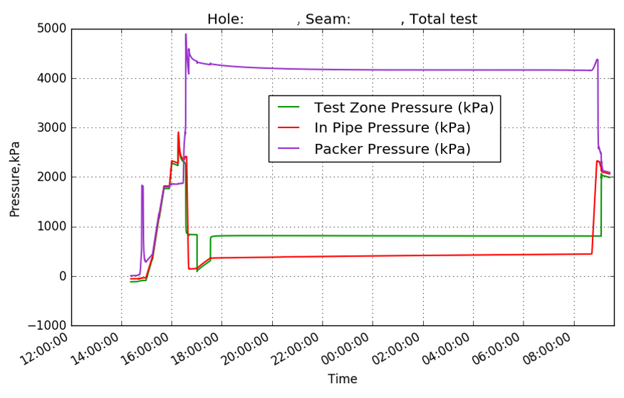
Issues associated with the Packer Test

The methodology of the packer test is that it should reach a steady state of fluid injection. If in fact it does so, it is an indication that the pressure drop between the rock and the fluid pressure within the hole are dominated by near well bore losses, typically by the size of the joint openings to and adjacent to the borehole.

The real information from such tests on the rock mass being tested is lost, because no attempt is made to determine the transient response of the ground.

Neither does the test provide information on the fluid pressure (head) within the ground, nor take this into account in how it affects the inflow rate.

Literature abounds on how to interpret such tests, and spurious correlations are published between the value of Lugeons and units of hydraulic conductivity, and by consequence, permeability.

We therefore have two tests that are widely used by the civil engineering industry which cannot provide the information that is required. Indeed, the results obtained are misleading, and their adoption could lead to serious errors in design. What can be done to remedy this?

The short answer is to change test methods.

Adopting the oilfield Drill Stem Test (DST) for civil and mining applications.

The most effective way to do this is to adopt the analogue of the oilfield DST for civil and mining applications. We have used these extensively for the coal seam gas and deep coal mining clients. We developed equipment and analysis to suit these applications.

The test needs a period of flow followed by zero flow from the test zone, during which pressure stabilisation is achieved. This is followed by an inflow period and then a period of no flow from the test zone, during which the pressure buildup is monitored.

This buildup time must be long enough to get a meaningful answer.

Low permeability ground tends to take a lot of time for the pressure recovery to deliver results with a useful measure of permeability. If there is no need to measure permeability down to low levels, then the test may be terminated early without providing precise value.

While flow from the test zone is the best choice, as it avoids contamination of the well bore with foreign fluids and clay particles, it is sometimes more practical to inject for a period at a constant rate, or by falling head, in the drill string. Changing the flow direction does not change the basis of analysis.

In Soil

These test techniques may be applied to soils, where the test may be conducted through a casing or standpipe, with the use of a downhole packer and pressure transducer to control flow. In rock, the equipment required to conduct a test comprises a single or straddle packer system, which incorporates a valve to control flow from the test zone.

Flow from the test zone is facilitated by purging the drill string of fluid prior to the test, or by running the tool into the hole with an empty drill string so that flow may occur into the drill string.

Pressures in the test zone need to be accurately logged, something that is relatively easy with the range of transducers and logging devices available.

Such tests can yield accurate information on permeability, and such features as barriers to flow or recharge boundaries within the ground. What they cannot do is provide information on the storage characteristics or the anisotropic nature of permeability.

To achieve this, other pressure sensing points (piezometers) must be installed.

This brings the testing process full circle, to one where a full pumping test might be used with at least three correctly placed piezometers to enable the determination of anisotropy in permeability and the storage behaviour.

The problem with this approach is that it is not possible to differentiate between anisotropy and inhomogeneity.

There is an alternative that enables the measurement of both inhomogeneity and anisotropy: Pulsed DST.

This involves sequentially testing individual boreholes and placing piezometers in these as each borehole test is finished. The next borehole to be tested sends a pressure transient to those boreholes drilled before and fitted with piezometers. The most convenient way to test each well is by conducting a DST in the test zones. Hence the name “pulsed DST”.

This method enables multiple measurements of mean permeability and directional permeability, so that both inhomogeneity and anisotropy may be assessed.

Guest Author: Mr. Ian Gray – BE, MAppSc, PhD, RPEQ, MAusIMM, SPE, Managing Director, Sigra Pty Ltd, Brisbane.

Acknowledgement: Geotechpedia team would like to thank Mr. Ian Gray, Sigra Pty Ltd, Managing Director for sharing this post through Geotechpedia.

Disclaimer: Any views or opinions represented in this post are personal and belong solely to the author and all content provided is for informational purposes only. Geotechpedia makes no representations as to the accuracy or completeness of any information on this post or found by following any link on this post.


Geotechpedia Online Survey Questionnaire Results

Picture1  “I like to listen. I have learned a great deal from listening carefully. Most people never listen.”                    

                                                                                                                                          Ernest Hemingway

First of all we would like to thank you all for participating in our online survey (16 June – 17 July 2016) regarding Geotechpedia’s future. As we truly value your opinion we made the first step forward for more interaction between us.

Survey Results

We managed to spread the news about Geotechpedia (34% of responses were from people visiting Geotechpedia for the first time) and at the same time we validated the fact that the majority of our users visit us on a need basis. This is logical since Geotechpedia is not a social website but a technical one and, frankly speaking, this is how we want to keep it! We are here to assist you with your queries when it comes down to geotechnical and mining engineering.

1 How oftenFurther to that, the survey results proved that publications, software and latest news sections are the most popular ones. Knowledge dissemination is our core value and we will keep striving our forces to provide you with the latest achievements in our industry.

2 Parts of Geotech

In terms of our site content we are happy to see that, as it stands at the moment, is covering most of the information our users are looking for (3.5/5) and considered to be of the highest quality (3.7/5) compared to other sites of similar content (3.7/5). However, that doesn’t mean that we are going to sit back and relax. We will keep on trying to provide you with the most recent and useful information in the industry.

Picture2


4 Information coverage 5 site content quality

6 other sitesYour overall rating for Geotechpedia (7/10) and the fact that you would be more than keen on recommending our website to a friend or colleague (3.9/5) shows that you do trust us and the results are encouraging us to keep on with the good work we believe we do.

7 overall rating 8 recommendation

Survey Demographics

Demo 1-age Demo 2 - gender Demo 3-Country


Demo 4-Level of Education


Demo 5-Employment status


Participants feedback

Finally, almost half of the participants (45%) reverted back to us with some really interesting and helpful comments.

The main request refers to more technical discussion. We have to admit that during the last few months our blog wasn’t as active as we would like it to be. For that reason, we have decided to inaugurate a new feature called “Geosysta short courses”. The new feature has been already released and its main purpose is to provide you with more technical information on engineering issues (case studies will be also included) and improve the technical connection between our users and ourselves.

Further to that and based on your comments, we will try to improve the appearance of our website (our web designers have already started their brainstorming!).

Another interesting remark was regarding the absence of a monthly newsletter which will inform you for the latest additions in our website. We are happy to say that having predicted that we just recently released our monthly newsletter (http://eepurl.com/b8N02X).

Finally, we received several requests for creating a geotechnical/mining conferences, symposiums, webinars agenda. We have to admit that this kind of information would be really useful and we will try updating Geotechpedia accordingly the soonest possible.

Thank you all once more and please do not hesitate to contact us directly at contact@geotechpedia.com.

The Geotechpedia Team

Geotechnical investigation data, always not enough?


IAEG XII congress
IAEG XII congress

This is a very controversial topic in which a straightforward answer is not possible. In this entry I would like to tackle some issues related to our own profession since we are responsiblefor the “acceptable” amount of investigation.

Recently I attended the IAEG 2014 (Engineering Geology) conference in Torino. In this conference numerous interesting topics of engineering geology and geotechnical investigation were covered. It was very interesting to note that in many cases a general conclusion was that not enough geotechnical investigation was executed prior to a geotechnical related failures.DSC_0527 geotechnical investigation


In conversations regarding the site investigation of a project it is very common to hear that “I would like additional investigation but the Client will not provide the funding” or that “the project finance does not allow for more or additional investigation, you have to do with what you have” etc. What do we do in such situations? We do what we have been taught as engineers to do, we overcome the problem. This means that either we accept a larger portion of liability, we either allocate the liability with statements like “additional investigation is warranted during construction” or we design very conservatively or all of the above. In any case, the design is based on limited information and it could go either way.

In many situations, due to the experience of the geotechnical designer or due to very conservative design assumptions no problems are manifested during construction or operation. But sometimes things go terribly wrong and somebody needs to take the blame, leading to long lasting litigations.

Is something wrong with the current practice? Everybody admires the great engineering attitude when nothing goes wrong and with limited investigation the project is completed. Even more, some of us proudly state “I saved so much by reducing the geotechnical investigation” but all this immediately changes when something goes wrong.

Maybe we should start thinking more as doctors? I don’t think anybody has gone with a medical situation and stated to the doctor that “I think you are asking too much medical testing” or “I don’t think an ultrasonic is warranted for my abdominal pain, cant you prescribe some conservative medicine that will make me better without doing all these expensive testing?” I would really like to see the face of the doctor hearing such negotiations. So why are we accepting such negotiations ?

Geotechnical engineering standard of care

November – December issue of Geo-Strata which is a published forum of the Geo-Institute of the American Society of Civil Engineers (ASCE) featured an article by Patrick C. Lucia, Chairman Emeritus of Geosyntec Consultants, titled “As I See It: Geotechnical Forensic Engineering in Defense of Geotechnical Engineers”.
In the article Patrick shares his over 25 years of experience in forensic geotechnical investigation of failures and the compliance of Geotechnical Engineers to “Standard of Care”. In his opinion the majority of failures occur due to “lack of process in conducting the geotechnical engineering practice”.


Unfortunately it is very difficult to standardize geotechnical engineering practice in a way that other engineering disciplines have. The difficulty of standardizing geotechnical practice is that ground is not standard. This is why geotechnical engineering is so challenging. How can you standardize an investigation in a new project? Is the text book “influence zone” depth an adequate depth to drill? Can a few centimeters thick unfavorable clay seam be found with two 30m borings in a proposed cut? Can an undisturbed or even remolded sample be acquired from that seam? Can we pursue the client to spend additional thousands of dollars when we are unsure of what lies beneath?
Pat is arguing that “when the process of engineering is properly done and properly documented, it will far reduce the number of claims and make the defense of those claims much easier.” This is true but maybe difficult, especially in a world of fast track projects and low bids. Maybe our profession needs to do much more to “standardize” proper engineering process. Firms may need to take action to “educate” potential clients and owners about the importance of a sound geotechnical investigation, peer reviewed process in ground properties evaluation and design and necessary time that is needed.
Time is a fundamental problem in geotechnical engineering profession. It is not easily understood why maybe a month is needed for a simple foundation investigation. How can you argue when you hear “we do not have such time, we need the results in a week!”, as if we control the permeability characteristics of a clay in a consolidation test!!!
These and many other issues make our profession so challenging, difficult but at the same time so rewarding, from a scientific point of view (I don’t know any billionaire geotechnical engineer). We need to practice geotechnical engineering and at the same time educate the rest of involved disciplines in its difficulties. Unfortunately probably we are not doing very well in the second part of educating…

Geosysta welcomes 2014

Geotechpedia 2014

Geotechpedia enters 2014 with the ambition to provide more geotechnical information and contribute to the geosociety with interesting and valuable publication links, software from the industry and equipment used in the sector.

Geotechpedia now has an updated look and feel more appropriate for today’s web. We hope we can make your experience more efficient and pleasurable at the same time while we save you precious time when searching for geotechnical information.


Register with Geotechpedia, and become a member of it’s online geotechnical community. It is very easy and safe, since it uses open ID. Geotechpedia does not request that you create yet one more password and will not store any.


By Registering you can rate all geotechnical information items provided in the site, you can review papers, software or equipment and you can add items in your favorite section.

Geotechpedia registered users page

Help others with your knowledge to get faster incite in our provided geotechnical information. Access your favorite items, review etc just by clicking on your user name in the top of the page

Geotechpedia and Geosysta wish you all a happy and productive new year.

Geosysta welcomes 2014