Tag Archives: geotechnical engineering

Geotechpedia reached a 1000 links on Geotechnical Software Applications!

Since 2012 Geotechpedia’s database is continually growing of geotechnical engineering information, including links for free geotechnical paper and publications, links for geotechnical equipment, hardware and heavy duty machinery, links for geotechnical software applications etc.

Geotechpedia team is now pleased to announce that a thousand links on Geotechnical Software Applications have been registered!

Each software is presented in Geotechpedia with its title, publisher, price, a small description summary, perhaps a photo or a video, tags and of course the link. There is a variety of categories i.e. Geology Software, Geotechnical Design Software, Mining, Structural etc.

Geotechpedia’s database includes catalogued free downloadable Geotechnical Paper and Publications and links for Geotechnical Equipment and Hardware.

This makes Geotechpedia an essential tool for those interested in geotechnical engineering. Since our goal is to constantly improve our quality of service, feel free to contact us for any comments or suggestions at https://geotechpedia.com/About/Contact


Geotechnical Risk Management

In our first ever post in Geotechpedia’s blog we tried to answer the most common question among professionals in the Geotechnical engineering industry “Geotechnical Investigation data, always not enough?”. In the specific post, it has been mentioned that “some of us proudly state “I saved so much by reducing the geotechnical investigation” but all this immediately changes when something goes wrong”. We are all aware of how limited or inadequate Geotechnical Investigation (GI) can affect both a project’s schedule and budget. In the following lines, we are trying to quantify these effects, provide guidance on how to easily create a risk scoring matrix and attributed risks, typical geotechnical risks and related mitigation measures.

Cost and time effect

Back in 1748 Benjamin Franklin stated “Time is money” in his “Advice to a Young Tradesman”. This quote finds application in all business sectors and the engineering one couldn’t stand out as an exception. In every project, delays are translated into cost and as such we are going to examine the estimated cost effects of delays deriving from inadequate Geotechnical Investigation on a project’s total construction budget. The most common chart when discussing the risk management in geotechnical engineering is presented below (Figure 1). It is obvious that for low values (1% approximately) of Geotechnical Investigation cost / tender cost (adjusted values), the total increase in construction cost may vary between 2% and 98% with an average value of 15-25%. When the Geotechnical investigation budget is slightly increased (adjusted Geotechnical Investigation cost / construction tender cost values between 2 and 4%) then the total increase in the construction cost drops to a typical range of 2% to 25% with an average value of 5-10%; meaning that an increase of 1-2% on the construction tender cost for additional Geotechnical Investigation signalizes a significant drop of approximately 25 to 50% (absolute values) in the total construction cost.

Figure 1: Total increase in construction cost related to adjusted Geotechnical Investigation cost / construction tender cost (source: UK Highways Agency projects (1994))

 Typical Risk Scoring Matrix

During the tendering procedure of a project, a risk assessment needs to be undertaken in order to evaluate the geotechnical risks at an early stage and propose mitigation measures. The following table (Table 1) presents a typical and simple scoring matrix that can be used in this kind of assessments and Table 2 details the specific risks associated with geotechnical works and categorizes them into probability of occurrence and cost/time impact.

The purpose of the following matrix is to help rank the key risks on site.

Table 1 Risk scoring matrix


Scores of 1-5 are allocated to the probability and impact in order to quantify and rate the risk rating. The risk scoring matrix should be used in conjunction with the priority action table detailed below (Table 2).

Table 2 Priority action table


Typical Geotechnical Hazards and recommended mitigation measures

Successful implementation of the suggested mitigation measures will assist with managing and reducing known risks to acceptable levels.

Table 3 below presents typical risks/hazards, related impact on construction budget and proposed mitigation measures.

Table 3 Risk/hazard assessment and proposed mitigation measures

In general, Geotechnical Risk Management gains supporters through the Projects Manager’s community since experience has proved that inadequate or incomplete Geotechnical Investigation during the tendering stage can have a severe impact on a project’s schedule and overall cost. Moreover, managing geotechnical risks also helps to increase safety levels in siteworks.

Conclusions

We need to keep in mind that geotechnical risk cannot be avoided and ignored but it can be managed and mitigated.

Taking all the above into consideration it is recommended that a detailed Geotechnical Investigation program is proposed at early stages of each project, following an in-depth desk study of all available information and site walk-over surveys.

It must be highlighted that the above post and its recommendations are to be read in conjunction with site specific available information and with critical thinking. In all cases, the Designer should set strict guidance for adequate Geotechnical Investigation in line with project specifications and international standards.

Useful References

[1] BS5930:1999, British Standard Code of practice for Site Investigations

[2] EuroCode 7 – IS EN 1997-2:1997 (Part 2, Annex B3)

[3] Clayton, C.R.I. (2001) Managing geotechnical risk, Thomas Telford.


Estimated Earth Pressures on Cut and Cover Sidewalls

Proposal for estimated Earth Pressures on Cut and Cover Sidewall in rock cuts

A common design issue many Geotechnical Engineers have come across in their career is the estimation of earth pressures on a Cut and Cover (C&C) sidewall located close to a rock cut. Usually, a C&C structure is designed and constructed close to an open excavation slope (supported or not) and then covered over with backfill material when construction of the structure is complete.

The specific course discusses a theoretical design case of a C&C in a stable rock cut and how the lateral earth pressures on the structure’s sidewall could be estimated.

Theoretical background on lateral earth pressures [1]

Active and passive earth pressures are the two stages of stress in soils which are of particular interest in the design or analysis of shoring systems. Active pressure is the limiting condition in which the earth exerts an outwards force stress on a retaining system and the members tend to move towards the excavation. Passive pressure is a limiting condition in which the retaining system exerts a stress on the soil with displacements towards the soil. Since soils have a greater passive resistance, the earth pressures are not the same for active and passive conditions. When a state of soil failure has been reached, active and passive failure zones, approximated by straight planes, will develop as shown in the following figure (level surfaces depicted) but at different displacements.

Figure 1

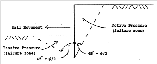
Figure 1: Limiting active and passive failure zones at different displacements

Two common earth pressure theories are:

-The Coulomb theory which provides a method of analysis that gives the resultant horizontal force on a retaining system for any slope of wall, wall friction, and slope of backfill provided. This theory is based on the assumption that soil shear resistance develops along a failure plane in the soil mass.

The wall friction angle (δ) value is always less than the internal angle of shear resistance (φ) one. It is common practice to assume a wall friction angle value of δ = 1/3 (φ) to 2/3 (φ). It must be noted that as wall friction increases, lateral earth pressured decrease.

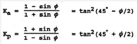
-The Rankine theory which assumes that there is no wall friction and the ground and failure surfaces are straight planes, and that the resultant force acts parallel to the backfill slope (i.e., no friction acting between the soil and the backfill). The coefficients according to Rankine’s theory are given by the following expressions:

ka_kp1

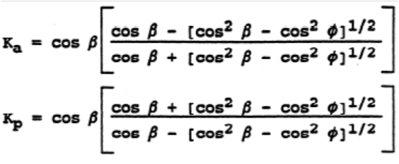
If the backslope of the embankment behind the wall is level (i.e., b = 0) the equations are simplified as follows:

ka_kp2

The above theories calculate earth pressures when an “infinite”soil mass exist behind the retaining system, but is this pressure the same when limited soil backfill is placed behind the retaining system? Such a case can be found in stable rock cuts with limited excavation behind the retaining wall.

Design Assumptions

As stated above, during the design stage of a C&C structure, the Geotechnical Engineer is commonly requested to provide the Structural Engineer with the estimated (active) earth pressures on the structure’s sidewall due to the backfill.

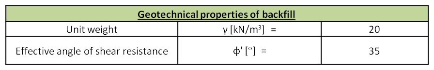
A typical cross section of a highway C&C which will be studied is presented in Figure 2, below. The geometry and geotechnical properties of the backfill area are given in Tables 1 and 2, respectively.

cs

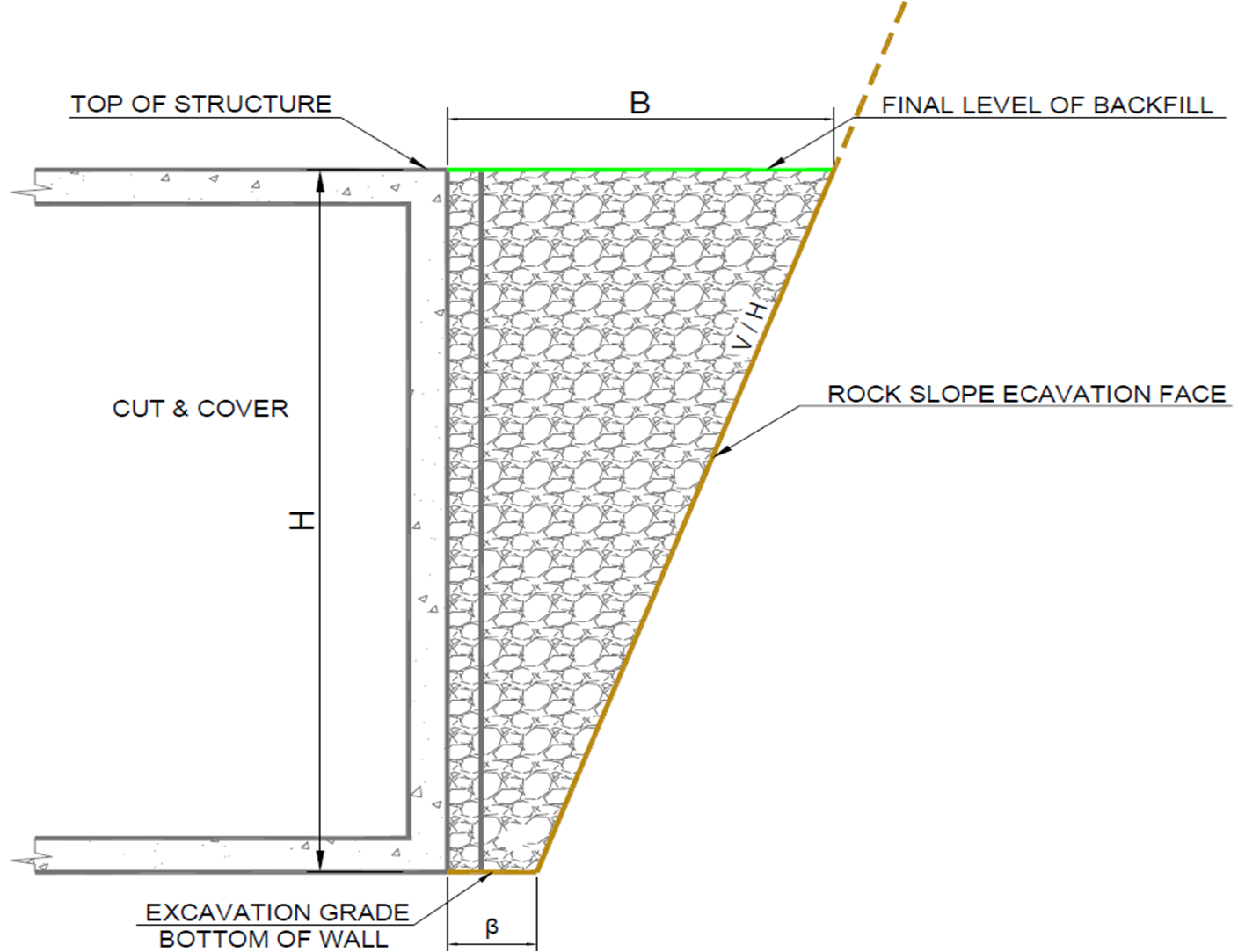
Figure 2: Typical cross section of a Cut & Cover at the backfill area

Table 1: Backfill geometry

Table 1

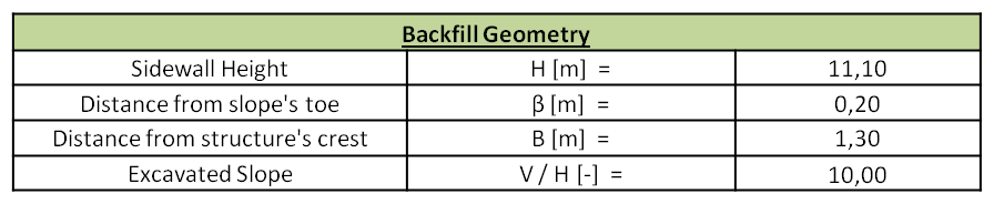
Table 2: Backfill geotechnical properties

Table 2

The geotechnical calculations are conducted under the assumption that the active earth pressures exerted on the sidewall derive only from the backfill material since it is considered that a stable rock cut or an in situ permanent soil nail reinforced wall exist, consequently, the corresponding slope earth pressures would be practically zero.

The interface friction angle between the backfill material and the sidewall was taken conservatively equal to zero based on the assumption that Expanded Polystyrene (EPS) will be applied on the sidewall.

Design calculations

Based on Coulomb’s theory, the forces acting on the C&C sidewall were the ones described below and presented in Figures 3 and 4.

-The backfill self weight (W). It must be noted that the self weight of the backfill material to be placed above the C&C roof slab was also taken into account.

-The resultant force (F) acting on the failure surface. The two components of that force are the normal force (N) and the friction (T). It must be noted that the sliding surface was considered cohesionless (c=0 kPa).

-The active earth pressure (Ρα) acting on the sidewall. Due to the presence of the EPS as described above, the resultant active earth pressure was considered acting normally on the sidewall.

-In the seismic design case, the normal inertia forces (normal and horizontal) of the backfill.Figure 3

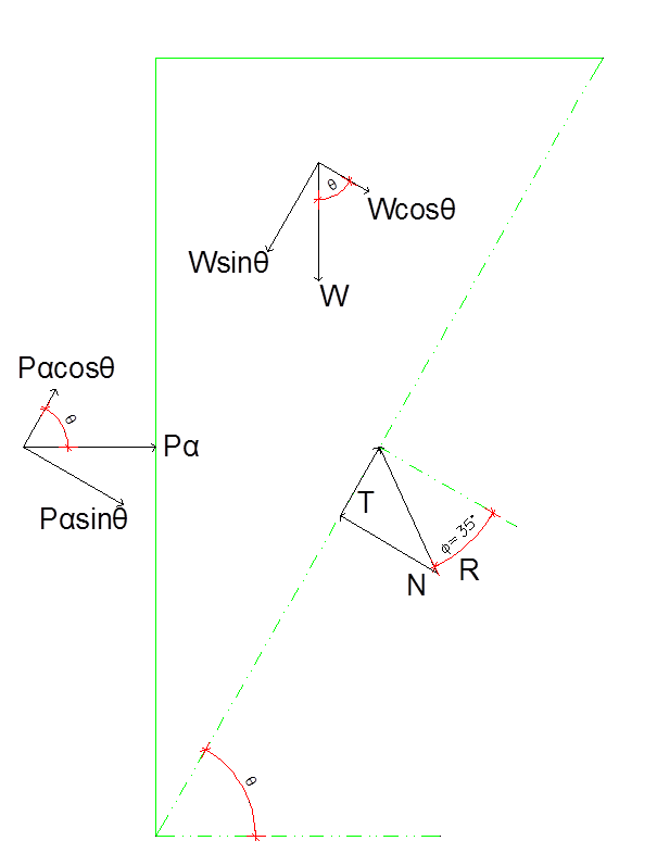
Figure 3: Forces acting on the C&C sidewall under static conditions

Figure 4

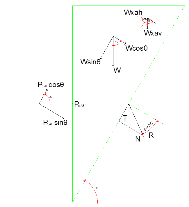
Figure 4: Forces acting on the C&C sidewall under seismic conditions

Due to the geometry of the backfill area and the aforementioned assumptions, the active earth pressures couldn’t be calculated under the assumption of a failure plane at 45°-φ/2. For that reason, a generic spreadsheet was produced for calculating the earth pressures for each straight failure plane.

The results in the form of charts are presented in the following Figures 5 and 6. Detailed input and output are shown in Figures 7 and 8.

Figure 5

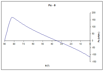
Figure 5: Active earth pressures per angle of failure plane diagram under static conditions

Figure 6

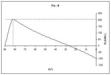
Figure 6: Active earth pressures per angle of failure plane diagram under seismic conditions

Figure 7
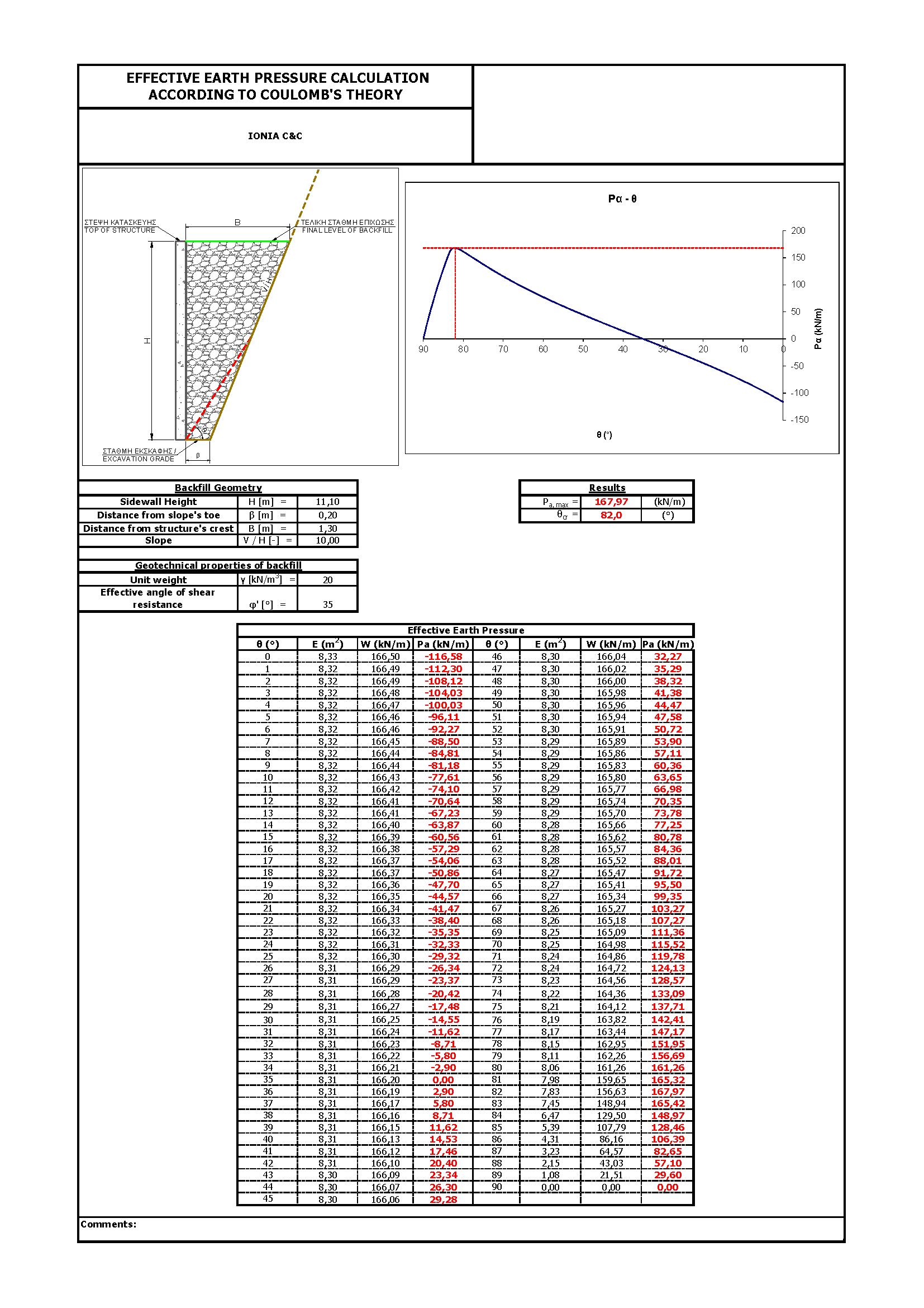
Figure 7: Active earth pressures per angle of failure plane diagram under static conditions

Figure 8
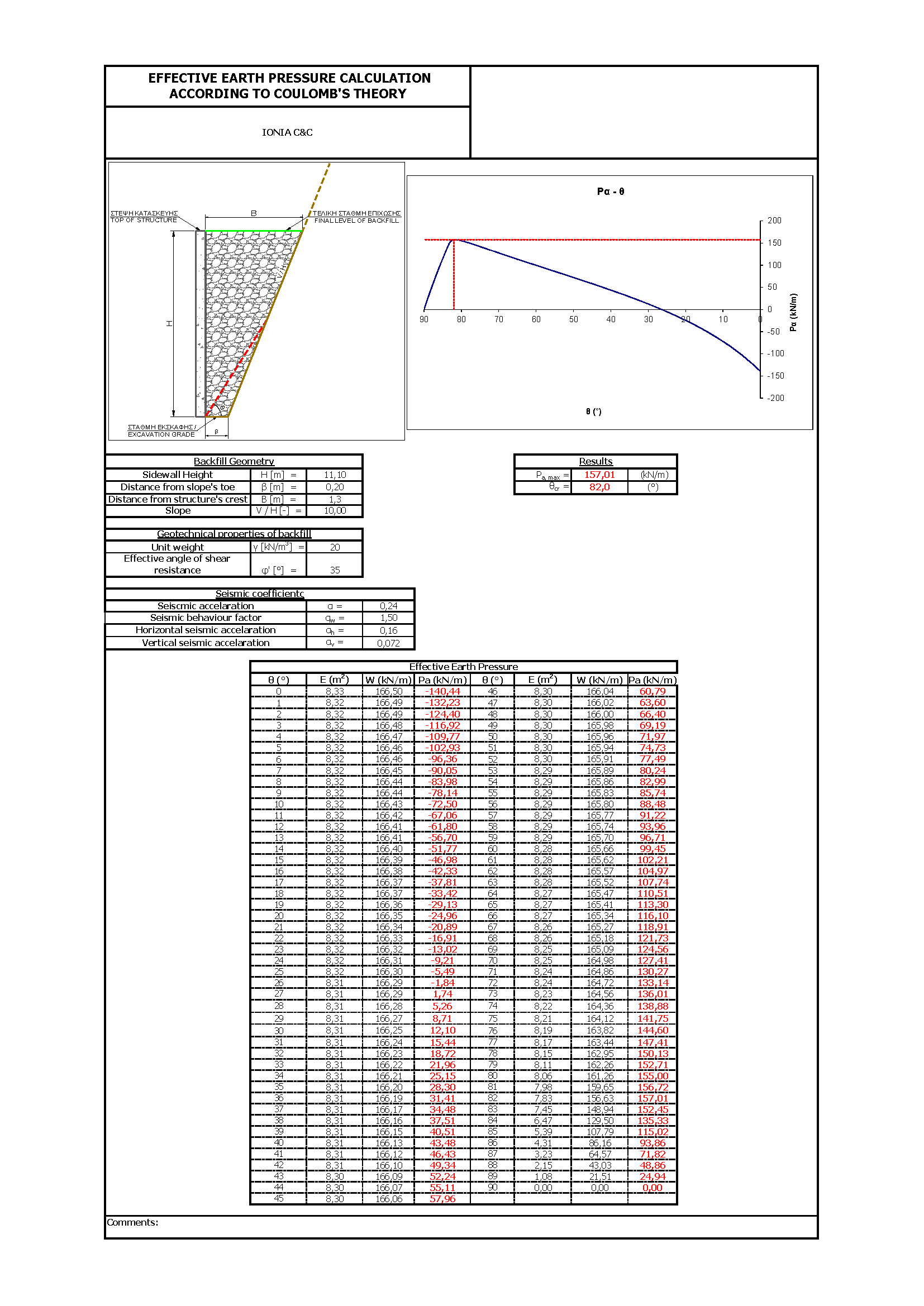
Figure 8: Active earth pressures per angle of failure plane diagram under seismic conditions

If the backfill geometry isn’t  taken into consideration and Rankine’s theory has been followed blindly, assuming that the failure plane would be at 45°-φ/2, a critical angle of θcr = 27,5° would have been calculated with a resultant pressure of Pa = 1/2xkaxγxH2 = 333,9kPa (static conditions). That means that the estimated earth pressures would be almost twice (100%) the probable ones leading to overdesign.

Conclusions-Recommendations

The estimation of lateral earth pressures on structures is a common problem in geotechnical engineering, especially in the case of complex geometries defined by other geotechnical designs (usually stabilization measures) in close proximity.

The specific note presented a theoretical design case where the estimation of active earth pressures and their magnitude following Rankine’s theory on a C&C sidewall couldn’t be established due to backfill complex geometry. A spreadsheet has been elaborated for design purposes in order to estimate, through repeated iterations, the critical angle of failure plane for which the maximum earth pressures on the structure occurred. The backfill material is considered to be of cohesionless nature without creeping phenomena.

There is never a rule of thumb and empirical approaches should be followed with engineering judgement since each design is unique and must always be treated as such.

It must be highlighted that the above note and its recommendations are to be read in conjunction with site specific available information and engineering judgement must be implemented in all design stages. Monitoring of earth pressures in such situations could enlighten more the theoretical approaches.

The views expressed in this note are only informative and should be used with great care in design situations.

References

[1] Steven F. Bartlett (2010), Examples of Retaining Walls. Earth Pressure Theory.

Geosysta at Klokova Tunnel Breakthrough (photos and videos)

A major milestone at Klokova tunnel has been reached on June 23rd, as part of IONIA Odos Motorway overall progress, with the breakthrough of the twin tunnel right branch (length: 2,900m approximately).

TERNA S.A. engineers tunneled through the final few meters connecting the two segments of the right branch on Thursday afternoon (23/06/2016), after less than 2-years since mobilisation which is considered a major achievement taking into account the difficulties met at several areas.

Geosysta Ltd, as part of the design team of the Austrian iC Consulenten ZT GesmbH, are responsible for the primary and final support of the Klokova tunnel, were invited to eye witness the breakthrough and be part of this milestone achievement.

We just couldn’t miss that…!

Initially, the rockmass was loosened with the use of explosives and afterwards, with the simultaneous use of two hydraulic hammers, TERNA people managed to bring down the final thin layer of bedrock standing between the two tunnel sides.

Seconds after blasting
Fig. 1: Seconds after blasting
Fig. 2: Tunnel back face after blasting

Watch the moment of the breakthrough from two different angles below.

MVI_4907

Klokova tunnel breakthrough

Fig. 3: Tunnel breakthrough
Fig. 4: Tunnel breakthrough
Fig. 5: Geosysta and iC personnel celebrating with TERNA personnel (from left to right) Georgia Papavgeri, Alexander Athanassiou, Chrysanthos Steiakakis

IONIA ODOS

IONIA ODOS will be connecting the entire Western Greece starting at Ioannina and following the western coastline of mainland Greece down to the Gulf of Corinth. At Rio, it crosses the gulf via the Rio-Antirrio Bridge. The new motorway is currently under construction and includes:

  • 196 km of a new, modern and high-standards motorway
  • 4 bidirectional tunnels of a total length of 11,2 km
  • 24 bridges of a total length of 7 km
  • 77 underpasses and 24 overpasses
(source: www.neaodos.gr/)

KLOKOVA TUNNELS

Klokova tunnel is located in the south-west of Aitolia- Akarnania region in Greece and, more specifically, at a distance of about 7km from the Rio-Antirrio Bridge. The current national highway alignment runs along the south outskirts of Klokova mountain.

Fig. 6: Wider area of project’s location (SW Greece / Aitolia – Akarnania)
Fig. 7: Existing national highway alignment along Klokova mountain outskirts
ScreenShot3
Fig. 8: View of the Rio-Antirrio bridge from the Klokova tunnel entry portal

Klokova tunnel project consists of a twin tunnel with an approximate length of 2,900m (RHT 2,913m and LHT 2,894m). The two horseshoe shaped tunnels are of an internal radius of 5.5m and a maximum width of 11.0m accommodating 2 traffic lanes of 3.75 and 3.5m, respectively. The maximum overburden height reaches 535m, approximately. Klokova tunnel is the longest one out of the four IONIA Odos tunnels (the other three tunnels are the Makinia, Ampelia and Kalidona ones).

Fig 6
Fig. 9: Klokova tunnel (Left branch)
Fig. 10: Klokova tunnel (Cross-passage area)
Fig. 11: Klokova tunnel (Cross-passage area)

Each tunnel section is being excavated in two stages. The upper semi-section is excavated first and then the excavation of the lower section follows. At the areas where poor quality rockmass is encountered the solution of invert at the bottom of the tunnel is implemented.

The excavation progresses with the use of explosives and hard ripping techniques are adopted at the areas where poor quality rockmass is encountered. Primary support follows the principles of the NATM.

Fig. 12, 13, 14, 15: Klokova tunnel (Final lining works)

Geosysta personnel are feeling proud of having participated in the majority of the design’s geotechnical aspects of this major infrastructure project.

Fig 11

Fig. 16, 17: Geosysta personnel on site (Georgia Papavgeri & Thanasis Leventakis)

Being on site during these very moments when our design comes into “life” is priceless to us.

geotechSYSTAThe Geosysta Team

Geotechnical investigation data, always not enough?


IAEG XII congress
IAEG XII congress

This is a very controversial topic in which a straightforward answer is not possible. In this entry I would like to tackle some issues related to our own profession since we are responsiblefor the “acceptable” amount of investigation.

Recently I attended the IAEG 2014 (Engineering Geology) conference in Torino. In this conference numerous interesting topics of engineering geology and geotechnical investigation were covered. It was very interesting to note that in many cases a general conclusion was that not enough geotechnical investigation was executed prior to a geotechnical related failures.DSC_0527 geotechnical investigation


In conversations regarding the site investigation of a project it is very common to hear that “I would like additional investigation but the Client will not provide the funding” or that “the project finance does not allow for more or additional investigation, you have to do with what you have” etc. What do we do in such situations? We do what we have been taught as engineers to do, we overcome the problem. This means that either we accept a larger portion of liability, we either allocate the liability with statements like “additional investigation is warranted during construction” or we design very conservatively or all of the above. In any case, the design is based on limited information and it could go either way.

In many situations, due to the experience of the geotechnical designer or due to very conservative design assumptions no problems are manifested during construction or operation. But sometimes things go terribly wrong and somebody needs to take the blame, leading to long lasting litigations.

Is something wrong with the current practice? Everybody admires the great engineering attitude when nothing goes wrong and with limited investigation the project is completed. Even more, some of us proudly state “I saved so much by reducing the geotechnical investigation” but all this immediately changes when something goes wrong.

Maybe we should start thinking more as doctors? I don’t think anybody has gone with a medical situation and stated to the doctor that “I think you are asking too much medical testing” or “I don’t think an ultrasonic is warranted for my abdominal pain, cant you prescribe some conservative medicine that will make me better without doing all these expensive testing?” I would really like to see the face of the doctor hearing such negotiations. So why are we accepting such negotiations ?

Geotechnical engineering standard of care

November – December issue of Geo-Strata which is a published forum of the Geo-Institute of the American Society of Civil Engineers (ASCE) featured an article by Patrick C. Lucia, Chairman Emeritus of Geosyntec Consultants, titled “As I See It: Geotechnical Forensic Engineering in Defense of Geotechnical Engineers”.
In the article Patrick shares his over 25 years of experience in forensic geotechnical investigation of failures and the compliance of Geotechnical Engineers to “Standard of Care”. In his opinion the majority of failures occur due to “lack of process in conducting the geotechnical engineering practice”.


Unfortunately it is very difficult to standardize geotechnical engineering practice in a way that other engineering disciplines have. The difficulty of standardizing geotechnical practice is that ground is not standard. This is why geotechnical engineering is so challenging. How can you standardize an investigation in a new project? Is the text book “influence zone” depth an adequate depth to drill? Can a few centimeters thick unfavorable clay seam be found with two 30m borings in a proposed cut? Can an undisturbed or even remolded sample be acquired from that seam? Can we pursue the client to spend additional thousands of dollars when we are unsure of what lies beneath?
Pat is arguing that “when the process of engineering is properly done and properly documented, it will far reduce the number of claims and make the defense of those claims much easier.” This is true but maybe difficult, especially in a world of fast track projects and low bids. Maybe our profession needs to do much more to “standardize” proper engineering process. Firms may need to take action to “educate” potential clients and owners about the importance of a sound geotechnical investigation, peer reviewed process in ground properties evaluation and design and necessary time that is needed.
Time is a fundamental problem in geotechnical engineering profession. It is not easily understood why maybe a month is needed for a simple foundation investigation. How can you argue when you hear “we do not have such time, we need the results in a week!”, as if we control the permeability characteristics of a clay in a consolidation test!!!
These and many other issues make our profession so challenging, difficult but at the same time so rewarding, from a scientific point of view (I don’t know any billionaire geotechnical engineer). We need to practice geotechnical engineering and at the same time educate the rest of involved disciplines in its difficulties. Unfortunately probably we are not doing very well in the second part of educating…

IAEG XII Congress: Engineering Geology

IAEG XII congressIAEG (International  Association for Engineering Geology) organizes the XII Congress that will be held in Torino (Italy) from 15 to 19 September, 2014. The topic of the IAEG XII Congress is: “Engineering Geology for Society and Territory” and aims to explore and analyze the role of Engineering Geology.


There are four main themes offered to participants:

  1. Environment: River Basins, Reservoir Sedimentation and Water Resources
  2. Processes: Landslide Processes, Marine and Coastal Processes,
  3. Issues: Urban Geology and Landscapes Exploitation, Preservation of Cultural Heritage
  4. Approaches: Applied Geology for major Engineering Projects, Education Professional ethics and Public Recognition of Engineering Geology

Deadline for abstract submission is fast approaching : 15/04/2013, while the estimated Deadline for Full Paper submission is September 30, 2013.

Geotechpedia reached over 3000 free publication links on geotechnical engineering!

Our database is a continually growing database of assorted geotechnical engineering information. Everyone interested in geotechnical engineering i.e. students, professionals, academics, can browse in geotechpedia’s free publications.

Taking into account the demands of geotechnical engineering, updating information is the crucial goal for us. We are proving this by continually increasing the number of free publication links.

fireworks-

Geotechpedia team is now pleased to announce that the number of free publication links that disseminate geotechnical knowledge is over 3000!

This means that Geotechpedia has cataloged over 3000 geotechnical publications in the database, including published papers, manuals, reports, dissertations etc.


Each publication is presented in Geotechpedia with its title, author, author’s organization, location, publication type, publication reference, tags, a small description summary and of course the link.

In our effort to provide professionals in geotechnical engineering with everything they need, the database includes catalogued geotechnical software and also geotechnical equipment.

Geotechpedia is the most integral and extensive geotechnical tool on line for everyone interested in geotechnical engineering! We will be happy to receiving your feedback concerning this project. Feel free to contact us and leave your comments!

Buildings collapse after subsidence in South China (Guangzhou)

On Monday afternoon (28/1/2013), three buildings collapsed after subsidence in Guangzhou. The incident happened near a metro tunnel construction site.

It is reported that metro workers spotted land subsidence near the project site and immediately the area was evacuated, hence no casualties have been reported. The subsidence area was about 10m deep and extended about 100m2.

It is also reported that the area is temporary stabilized by backfilling concrete into thesubsidence. The site is monitored for risk assessment.

(Source: http://www.chinadaily.com.cn)

Tunnel construction with a fast pace and lowered standards could lead to disaster. Land subsidence can be caused by a variety of factors. Tunneling in urban areas always includes careful consideration and monitoring of land movement.

subsidence causes buildings collapse in china