Category Archives: soil mechanics

New era in site investigation data access

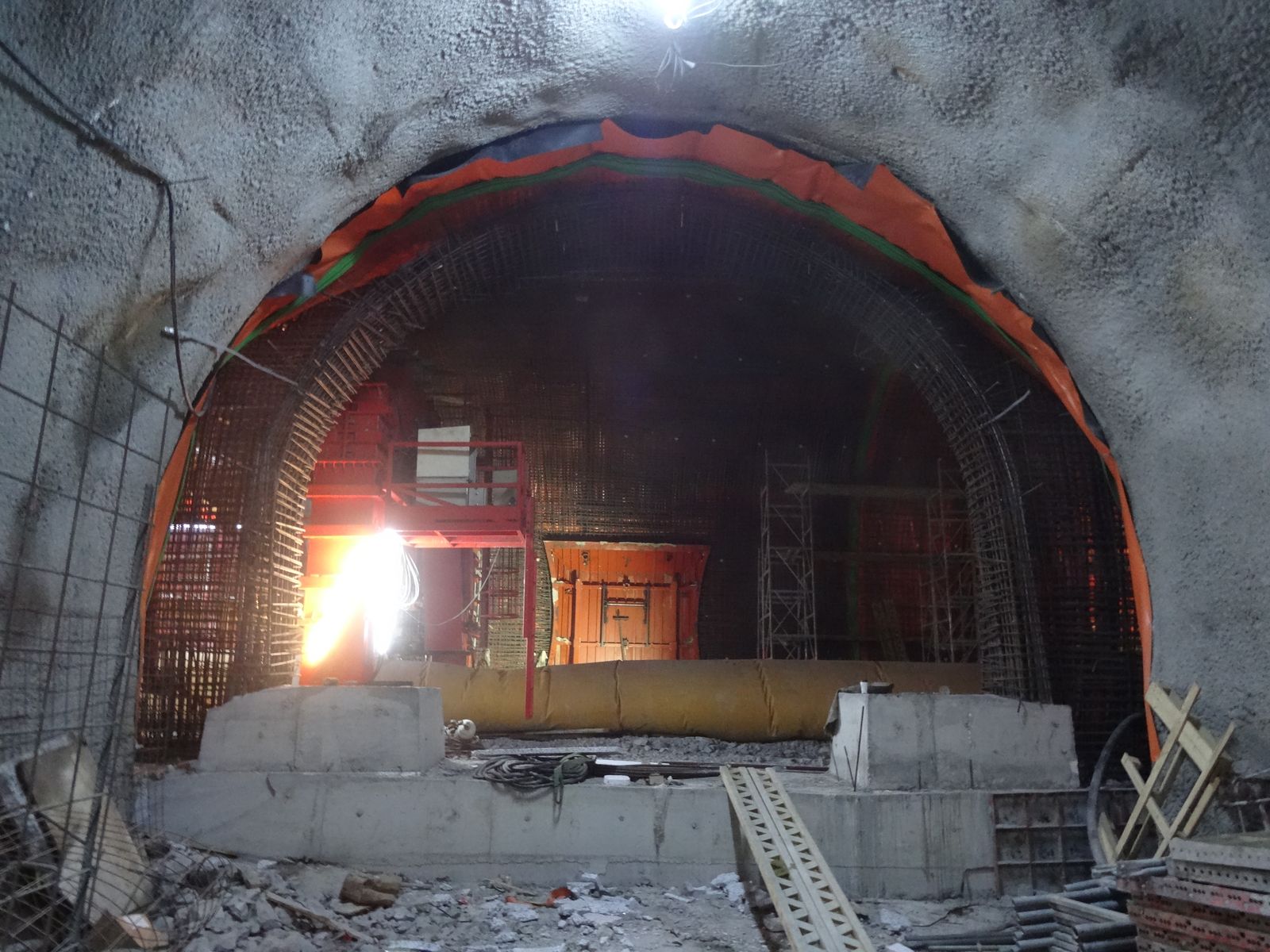
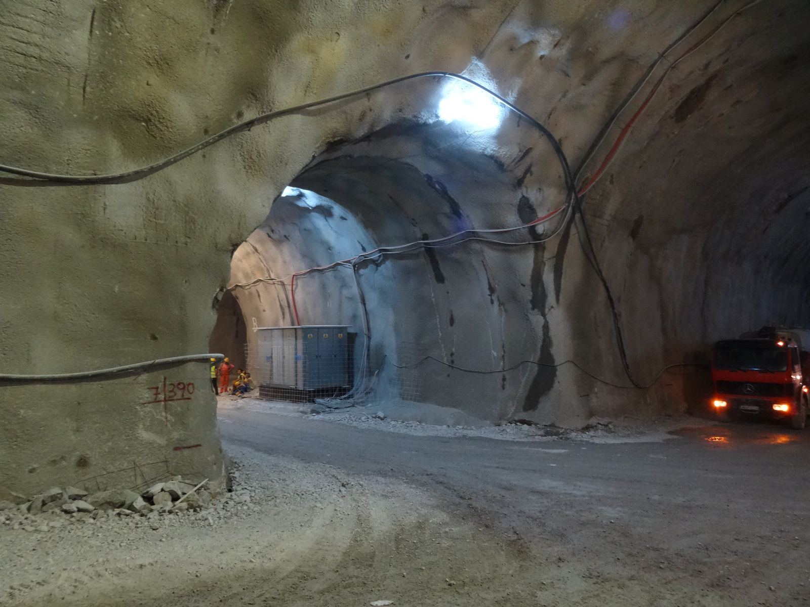
Our industry is a bit behind when it comes to new technologies, maybe it is because the scientific progress is moving slowly or not even significantly changing with time. For instance, we’re all still using Terzaghi’s early 1940’s one dimensional consolidation theory or the SPT to conduct our soil investigation. SPT was standardized between 1920 – 1930 and is still in practice today with minor modifications.

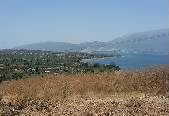
We need to explore new technologies in every part of our profession, from site reconnaissance with the use of satellite imagery or drones, to databases for site investigation and monitoring. We need to accept that technology is evolving rapidly and we should adjust and adopt, we need to go forward!

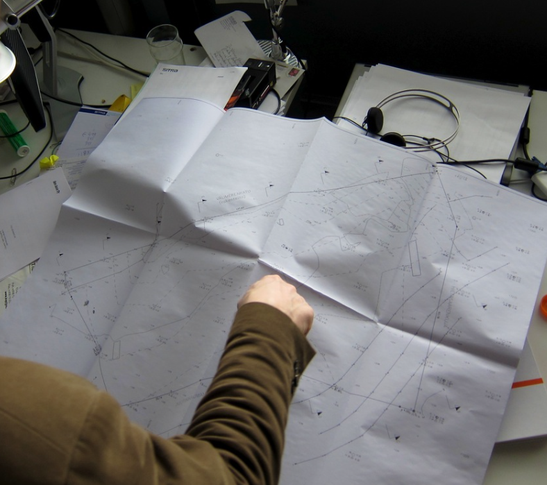
We still prepare site investigation reports in a static manner, we may use software to prepare them but in the end the reports and information they include is limited, without online cross references or procedures to easily update them with new or additional data. Maybe it is time to change?

Wouldn’t it be much easier if we could store our site investigation data electronically even from the field?

Wouldn’t be much more efficient if we could correlate different data or data from different locations or from different tests with a click of a button?

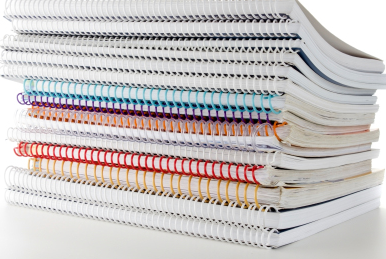
Why should we still be buried in thick reports, long sheets of borehole data, difficult to find or correlate and in the end to evaluate them? We are living in the google search era, we are used to type one word or one phrase and expect to have results in a few milliseconds. We should go forward!

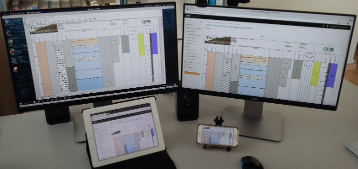
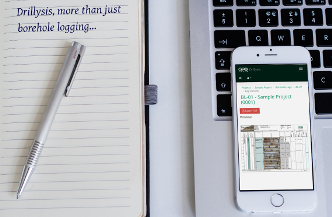
It is time that we utilize new and available technology, utilize the power of easily accessed databases, the power of the cloud, being able to have access of our data from anywhere, from our laptop, from our tablet, even from our smartphone.

We need to be able to easily find in our data what we are looking for with a simple search box, just type a drilling name, or view in google maps our investigation area and have a quick look of the locations of our drillings in relations with structures, landforms etc. We need to press one button or tap our finger at the screen and access the information we are looking for. We need to be able to represent investigation data in different formats, for different people and different disciplines. Geologists may want to see information that engineers think is useless. Hydrogeologists may want to view a vast number of water chemical analysis next to the geological description of the ground, this is something that a geotechnical engineer would not appreciate much, he would prefer to see his laboratory index and strength tests. The mining reserve engineer would like to see his ore and mineral percentages. We don’t need to prepare different printed reports or different borehole logs for different disciplines any more.

We can now centrally store all our investigation data and then very easily select what we need to correlate with what or what type of information we want to see next to other information. We can do it from our tablet or smart phone.

We can be in a meeting and just tap in our smart phone the drilling we want and see any information we have stored in it in a very easy way. This technology is here and we should consider how it will increase our productivity and efficiency.

Evenmore, maybe very useful information could come out when you see different data placed together, which is very hard with printed reports. The geotechnical engineer gets his own format, the hydrogeologist his, this can stop today. Technology is here and we can easily adapt.

Geosysta at Klokova Tunnel Breakthrough (photos and videos)

A major milestone at Klokova tunnel has been reached on June 23rd, as part of IONIA Odos Motorway overall progress, with the breakthrough of the twin tunnel right branch (length: 2,900m approximately).

TERNA S.A. engineers tunneled through the final few meters connecting the two segments of the right branch on Thursday afternoon (23/06/2016), after less than 2-years since mobilisation which is considered a major achievement taking into account the difficulties met at several areas.

Geosysta Ltd, as part of the design team of the Austrian iC Consulenten ZT GesmbH, are responsible for the primary and final support of the Klokova tunnel, were invited to eye witness the breakthrough and be part of this milestone achievement.

We just couldn’t miss that…!

Initially, the rockmass was loosened with the use of explosives and afterwards, with the simultaneous use of two hydraulic hammers, TERNA people managed to bring down the final thin layer of bedrock standing between the two tunnel sides.

Seconds after blasting
Fig. 1: Seconds after blasting
Fig. 2: Tunnel back face after blasting

Watch the moment of the breakthrough from two different angles below.

MVI_4907

Klokova tunnel breakthrough

Fig. 3: Tunnel breakthrough
Fig. 4: Tunnel breakthrough
Fig. 5: Geosysta and iC personnel celebrating with TERNA personnel (from left to right) Georgia Papavgeri, Alexander Athanassiou, Chrysanthos Steiakakis

IONIA ODOS

IONIA ODOS will be connecting the entire Western Greece starting at Ioannina and following the western coastline of mainland Greece down to the Gulf of Corinth. At Rio, it crosses the gulf via the Rio-Antirrio Bridge. The new motorway is currently under construction and includes:

  • 196 km of a new, modern and high-standards motorway
  • 4 bidirectional tunnels of a total length of 11,2 km
  • 24 bridges of a total length of 7 km
  • 77 underpasses and 24 overpasses
(source: www.neaodos.gr/)

KLOKOVA TUNNELS

Klokova tunnel is located in the south-west of Aitolia- Akarnania region in Greece and, more specifically, at a distance of about 7km from the Rio-Antirrio Bridge. The current national highway alignment runs along the south outskirts of Klokova mountain.

Fig. 6: Wider area of project’s location (SW Greece / Aitolia – Akarnania)
Fig. 7: Existing national highway alignment along Klokova mountain outskirts
ScreenShot3
Fig. 8: View of the Rio-Antirrio bridge from the Klokova tunnel entry portal

Klokova tunnel project consists of a twin tunnel with an approximate length of 2,900m (RHT 2,913m and LHT 2,894m). The two horseshoe shaped tunnels are of an internal radius of 5.5m and a maximum width of 11.0m accommodating 2 traffic lanes of 3.75 and 3.5m, respectively. The maximum overburden height reaches 535m, approximately. Klokova tunnel is the longest one out of the four IONIA Odos tunnels (the other three tunnels are the Makinia, Ampelia and Kalidona ones).

Fig 6
Fig. 9: Klokova tunnel (Left branch)
Fig. 10: Klokova tunnel (Cross-passage area)
Fig. 11: Klokova tunnel (Cross-passage area)

Each tunnel section is being excavated in two stages. The upper semi-section is excavated first and then the excavation of the lower section follows. At the areas where poor quality rockmass is encountered the solution of invert at the bottom of the tunnel is implemented.

The excavation progresses with the use of explosives and hard ripping techniques are adopted at the areas where poor quality rockmass is encountered. Primary support follows the principles of the NATM.

Fig. 12, 13, 14, 15: Klokova tunnel (Final lining works)

Geosysta personnel are feeling proud of having participated in the majority of the design’s geotechnical aspects of this major infrastructure project.

Fig 11

Fig. 16, 17: Geosysta personnel on site (Georgia Papavgeri & Thanasis Leventakis)

Being on site during these very moments when our design comes into “life” is priceless to us.

geotechSYSTAThe Geosysta Team

ISSMGE Paris 2013. What did you miss?

A brief feedback from Chrys Steiakakis

A brief summary  for all the people that could not make it to the 18th International conference on soil mechanics and geotechnical engineering held on Paris between Monday 2 and Friday 6th of September 2013. The conference main theme was “Challenges and Innovations in Geotechnics”.

The conference commenced with the former president J. L. Briaud presentation of “The State of the Society” in which a very interesting point was his 10 rules for success.

J. L. Briaud presentation of “The State of the Society”

The conference continued with the 8th Terzaghi Oration invited lecture from Susan Lacasse of the Norwegian Geotechnical Institute (NGI).

Susan Lacasse presentation “Protecting society from landslides – the role of the geotechnical engineer”

The title of the lecture was “Protecting society from landslides – the role of the geotechnical engineer”. The lecture presented case studies of landslides, their causes and the way they were analyzed and treated. Very interesting was the Kattmarka landslide that occurred on March the 13 2009 (which incidentally was Friday the 13!) and was caused because of the road construction. Main issues that led to the landslide were among others the limited geotechnical investigation and geotechnical design.

The first day continued with the Ishihara lecture presented by George Gazetas from the National Technical University of Athens (NTUA). The presentation title was “Soil-Foundation-Structure systems beyond conventional seismic failure thresholds”.

George Gazetas presentation “Soil-Foundation-Structure systems beyond conventional seismic failure thresholds”

He presented a novel approach of designing shallow foundations that are not designed to behave elastic in earthquake loading but to be able to work in extreme conditions and allow for uplift and bearing capacity slippage with acceptable limits of temporary and permanent deformations (settlements). This approach is contrary to current codes but it was shown that it could avoid structural damage and collapse.

The conference continued with the Manard Lecture presented by J. L. Briaud with title “The pressuremeter test: Expanding its use” in which he explained how to correctly utilize the PMT, how to execute the drillings and what the advantages of the pressuremeter test are. Furthermore he gave some reference values for preliminary design and some further extend of the test in liquefaction.

J. L. Briaud presentation “The pressuremeter test: Expanding its use”

A.Sim of Soletanche-Bachy provided an excellent presentation regarding the construction challenges and difficulties for the new Bugis Station and associated tunnels for the Mass Rapid Transit in Singapore.  Especially interesting were the methods used to overcome the passage of the tunnels and the station under or very near buildings.

A.Sim of Soletanche-Bachy presentation

Professor R. Jardine of Imperial Collage presented the Bishop Lecture in which he presented a state of art of laboratory testing and the use in research and practice. The lecture covered driven piles in sand and the detailed laboratory evaluation of these sands in order to predict pile behavior in static and cyclic loading.

Professor R. Jardine presentation Bishop lecture

The conference continued the next day with very interesting invited lectures that will be presented in a following entry.

Mohr – Coulomb failure criterion continued

Things to remember when using the Mohr – Coulomb failure criterion:

  • The linear failure envelope is just an approximation to simplify calculations
  • The failure envelope is stress dependent and will produce some kind of curvature if shear strength tests are executed in much different confining stresses (fig 1, from Duncan and Write, 2005).


  • According to Lade, 2010 the failure envelope is curved and at low effective stresses which can be found in superficial failures on slopes, the use of linear Mohr – Coulomb may be in the unsafe side. Soils without cementation do not provide any effective cohesion in very low effective stresses (fig 2, from Lade, 2010).


  • When the linear Mohr – Coulomb criterion is used it must be evaluated for the expected stress range in the field.
  • Small cohesion values will not produce significant errors when high effective stresses are anticipated in the calculation.
  • In low effective stress even minimum values of effective cohesion (in cohesionless soils) can produce significant errors in factor of Safety (FS) calculations.

References:

Duncan J. M.,  Wright S. G., (2005). “Soil Strength and Slope Stability”. Wiley, New York.

Lade P. V. (2010). “The mechanics of surficial failure in soil slopes”. Engineering Geology 114, pp 57-64.

The Mohr – Coulomb strength criterion

This is something that all geotechnical engineers should know but it is surprising how many do not! Just a brief overview of how the Mohr – Coulomb strength criterion came about.

The Mohr – Coulomb criterion is the outcome of inspiration of two great men, Otto Mohr born on 1835 and passed away on 1918 and Charles-Augustin de Coulomb born on 1736 and passed away on 1806.

The two men never coexisted but their brilliant minds contributed significantly in the scientific knowledge. The combination of two hypotheses gave us the Mohr – Coulomb failure surface.

Chronologically,  Coulomb was involved in military defense works (how much knowledge have we gained due to war!) trying to built higher walls for the French. In order to investigate why taller walls than usual were failing and try to built them to stand, he wanted to understand the lateral earth pressure against retaining walls and the shear strength of soils. He devised a shear strength test and observed (at that time, with his tests) that soil shear strength was composed of one parameter that was stress – independent named cohesion (c) and one that was stress – dependent, similar to friction of sliding solid bodies named angle of internal friction (φ). Probably he executed shear strength tests and found for different normal stresses (σ) different shear stresses (τ). By plotting these data on a (τ-σ) diagram he obtained the straight line denoted by the equation τ=c+σ.tan(φ) as can be seen in the next figure.

Coulomb failure surface

Mohr (1900) proposed a criterion for the failure of materials on a plane which has a unique function with the normal stress on that plane of failure. The equation for that was τ=f(σ) where τ is the shear strength and σ the normal stress on the plane.  With the use of the Mohr circles which is a two dimensional graphical representation of the state of stress at a point and the circumference of the circle is the locus of points that represent the state of stress on individual planes the Mohr failure envelope was proposed. The Mohr envelope was a line tangent to the maximum possible circles at different stresses and no circle could have part of it above that tangent curved line. (figure 2).

Mohr failure envelope

It is not known (Holtz et al, 1981) who first combined both theories but combining the Mohr failure criterion with the Coulomb equation gave a straight line tangent (to most of the Mohr circles) and the Mohr – Coulomb strength criterion was born (figure 3).

Mohr - Coulomb failure criterion

Holtz R. D., Kovacs W. D., (1981). “An Introduction to Geotechnical Engineering”, Prentice Hall.