Tag Archives: embankment

Yeager airport landslide

Yeager Airport Expansion slide additional comments

In my previous entry regarding the Yeager airport landslide where I hypothesize for a possible shear zone somewhere near the foundation, I got some interesting comments from fellow engineers. In this entry I would like to clarify some issues.

The hypothesis made about a shear zone was based on published information regarding intercalation of sandstone and shale and photograph observations of the area. A possible dormant landslide was hypothesized by other contributors in the ASCE group in LinkedIn. The model I presented was very simplified in order to test the possibility of the shear surface hypothesis. I will come back to the model with some more details, but I wouldn’t like to deviate from the failure discussion to a model discussion.

I stated previously that usually failures of such large magnitude are more complex and significant data and observations are required to understand the real mechanism. This I am sure will be dealt with by enquiry committees, forensic consultants etc.

I based my hypothesis considering that the Designers of the reinforced earth had done a good job, that the materials used were of appropriate quality and that something outside the structure was responsible or partially responsible for this failure. Many have commented regarding the reinforcement design and all are valuable comments which I will not reply but can be found here. Before a detail analysis and modeling of the failure is possible, additional hard data are required, such as shear strength properties of the actual soil, current tensile strength of the geogrid (as found in the landslide area), excavation at the toe of the slope etc. Until such data become available, only hypothesis can be made that may be completely wrong in the end.

The reason why I made the hypothesis of a shear zone is because it is based on previous information about older landslides in the area, because shale is notoriously tricky material when combined with sandstone and to broaden the possibilities of failure outside the earth structure.

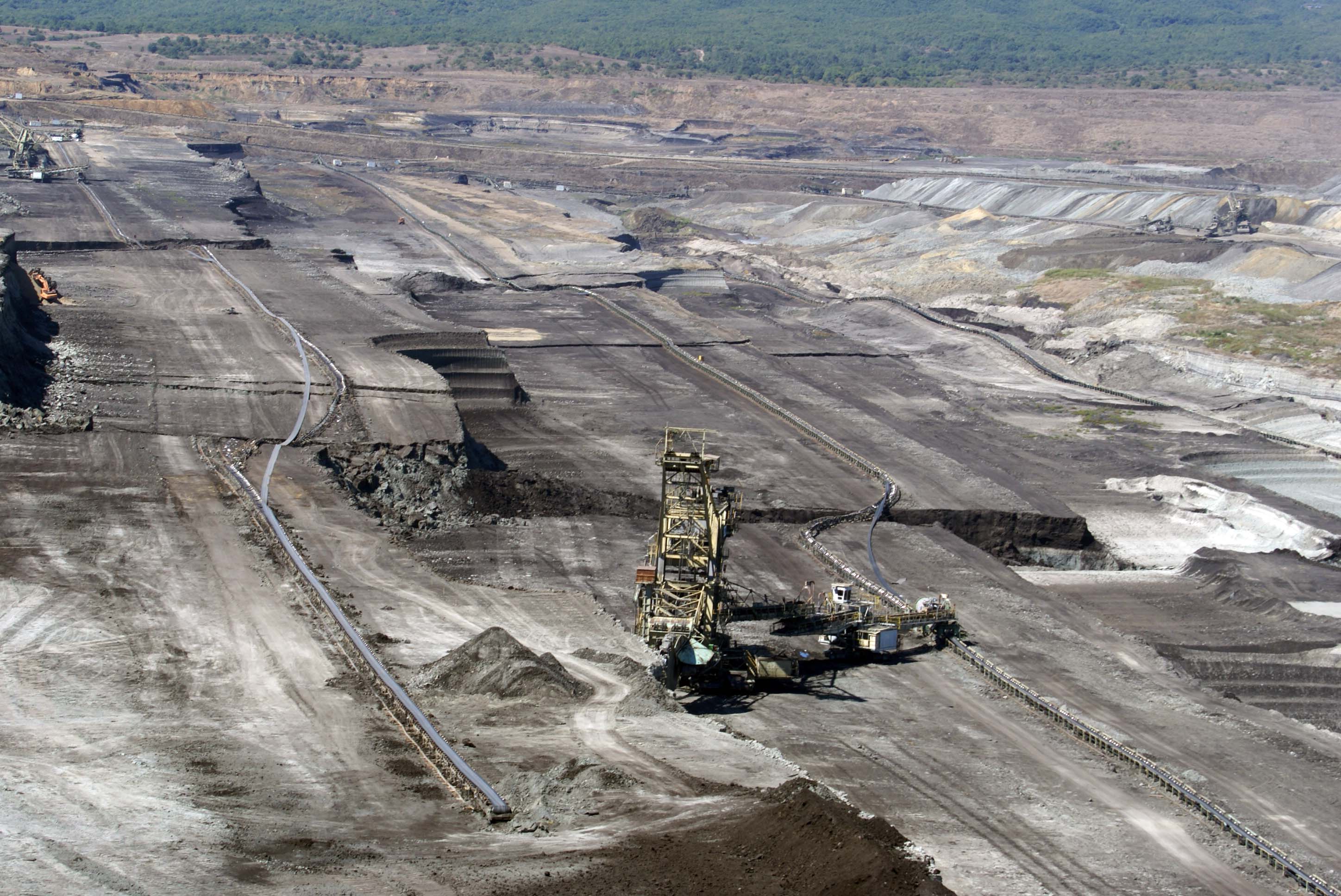
Many times, failures are formed due to very thin weak layers which are very difficult to identify during ground investigation. Sometimes zones (or layers) of a couple of centimeters can be responsible for extended failures. Such zones many times are ignored, especially in very large structures. Consider a borehole of 50-100m with a low strength shale zone of a couple of centimeters, is it always possible to identify it? Even if not ignored, during investigation, a shale zone could appear strong and competent. In the following photograph a translational failure on a lignite mine can be observed. The failure took place on a clayey shale layer of couple of centimeters in a nearly horizontal stratification material. Observe the magnitude of the failure in relation to the huge bucket wheel excavators. Also observe the horizontal movement based on the misalignment of the conveyor belts. The slope inclinations before failure were very shallow, around 1:3 (V:H).

Mine landslide Geotechpedia
Mine landslide

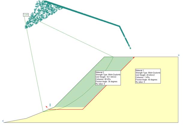
Coming to the slope stability model I used, it was only to validate the possibility of such a failure and not to model the actual reinforced earth slope and its failure. The parameters used were the ones provided by the Lostumbo 2010 presentation and instead of including the reinforcement, a cohesion was used to produce a factor of safety above 1.3 for a circular shear surface inside the soil reinforced structure. A shear surface was not included and a factor of safety above 1.3 was selected because it is assumed that the structure would have been designed above this FS. It is not the intention to assume a soil material with such cohesion. The initial calculation to validate the stability of the model before the failure surface is presented in the following figure.

Slope model
Slope model

But once again I hope the discussion will not deviate from the actual issue and get focused on the model. As R. Peck very elegantly notedstability analyses are tools for the guidance of the investigator. They have their limitations with respect to evaluating the stability of existing dams [the paper was about dam failure] It is not meant that they should never be performed. However, the numerical values for the factor of safety should carry little if any weight in judging the actual safety of the structure with respect to catastrophic failure”. Peck was evaluating a dam failure, and he focused on other issues that play important roles in relation to failures. So in that context I (among others) proposed the lower shear failure or old landslide issue as part of the controlling factors. Hopefully soon we will have many additional hard data to address this issue.

Finally I would like to note that earth retaining structures are a very good solution to many situations and we should not be reluctant to use them because of such incidents. We should though learn about such failures and put all our effort to avoid them in the future.

References:

R. Peck, (1998). “The Place of Stability Calculations in Evaluating the Safety of Existing Embankmnet Dams”, Civil Engineering Practice, Fall 1998.

Yeager failed slope

What could have gone wrong in Yeager Airport Expansion slide?

Yeager airport landslide

Recent news and photographs present the spectacular slide that occurred in the Yeager Airport Expansion Runway 5. The slide occurred in the South slope which was among the highest if not the highest (~74m) reinforced earth slope in the US. The project had received the award of Excellence – TenCate Geosynthetics in 2007 International Achievement Awards. According to FHWA Manual the Yeager Airport in Charleston WV had been constructed as a massive earthwork in 1940’s. The mountainous conditions around the airport produced steeply dipping slopes to the Elk and Kanawha Rivers. In order to meet FAA Safety Standards runway 5 required a 150m extension in order to create an emergency stopping apron. The most cost effective solution was a 74m high 1H:1V reinforced steepened slope (RSS). The chosen solution is presented in Figure 1 taken from Lostumbo 2010.

2010 STGEC - Yeager Airport - Tallest Reinforced Slope in N America
Figure 1: Reinforced 1:1 earth slope extension of runway 5

As can be seen from Figure 1, most of the reinforced earth area is above the original ground and only a small part in the slope base is excavated in order to found the reinforced earth structure. Based on Lostumbo, 2010 over 100 borings were performed, with extensive laboratory testing and the final outcome was that the site consisted of primarily fill, colluvial and shallow rock. The material parameters used for the bearing soil zone were unit weight γ=22kN/m3, φ’=40ο and c’=0kPa. I would like to provide some speculations regarding this incident based on the available data found on line and photographs from the news and Google earth. I must point out that these are only speculations since no official data are available to me, nor the exact design or construction plans. These speculations are made just by observations and engineering imagination!   I am sure that significant investigation will take place in the coming months and years which will produce the actual conditions and reasons for this spectacular failure. A picture from Google earth taken on 9/2005 presents the initiation of excavation for the construction of the reinforced earth slope.

Yeager SW slope copy
Figure 2: Google earth image of excavation at Southwest slope of runway 5

A newer picture taken on 4/2006 presents the progress of works in which a part of the reinforced earth slope has been constructed.

Yeager airport partially constructed slope
Figure 3: Google earth image with partially constructed slope

It is very interesting to note that the excavation and foundation of the earth structure did not go all the way to the base of the hill. It is possible that good foundation material (assuming rock) was found in some elevation and was considered appropriate for founding the structure. After all the large earth structure is placed on sound rock (mostly sandstone) with a compressive strength between 30-95MPa! Weathered sandstone from the borrow area had a friction angle between 38.9-39.6o. The placement of the reinforced earth structure on top of bedrock can be observed in figure 4. The bedrock is clearly visible in the back and some moisture can be observed a bit higher in the slope.

Is the “competent” foundation bedrock to blame?, is the design of the reinforced slope to blame? Is the construction practice? Is the intense rainfall? Usually many factors contribute to such a large failure, but at this point with very limited information I would like to focus on the bedrock conditions and the fill material placed on the bedrock.

Yeager airport reinforcement placement
Figure 4: Site photograph shown the placement of reinforcement near the base of the slope, rock formation is clearly visible in the back (Lostumbo 2010).

Is a sound bedrock always appropriate for placing such a large structure? Based on the unconfined compressive strength I would say yes, but are other conditions at play here? Based on Huang et al, 2014the on-site geomorphology consisted of weathered sandstone underlain by sandstone and some shale.” and “The compressive strength of the rock foundation varied from 30MPa to 95MPa. The high bearing capacity of the underlying sandstone foundation and the high friction angle of the onsite weathered sandstone soil meant that the extent of the reinforced slope could be kept to a minimum, and maximum use could be made of the onsite soil.”

Notice the phrase “sandstone and some shale”. Could this simple phrase be the key for what happened? It is well known that even small intercalations of shale can produce enormous geotechnical problems as was the case of Landslide on No.3 Freeway in Taiwan (Duncan, 2013). The first reason is that shale materials have much lower compressive strength but more importantly considerably lower friction angle. Furthermore if not fractured, they present a very low permeability barrier. Usually water is seeping in the sandstone – shale interface, asymmetrically weathers the shale and also produces increased pore pressures in that interface. Could such an interface (or failure surface) had been formed in this case? The answer is, it may be possible and can be seen in the following very simple model in figure 5. (will not go into much detail about the model it is just an example of the possible formation of such a failure surface).

Yeager airport slide model copy
Figure 5: Very simple model evaluating the possibility of failure due to weathered shale intercalation

Now let’s go back to actual observations, figure 6 is a Google earth image taken on 3/2012. Please observe the stones between the slope and the road in the red circle. Then let’s go to Google street view in the same location and what we see is shown in figure 7. The layering of the bedrock is clearly visible, furthermore some form of fissure can be observed even with some horizontal movement one can argue based on this image. Could such a feature or a similar one in different elevation be the weakest link of this structure? Could it have been in marginal stability and all it took was some heavy rainfall that increased the pore pressures in this interface and initiated the slide? Food for thought until the actual investigation comes out and the real conditions that lead to instability, which I really hope are much more complex, can be addressed.

Yeager airport google earth 1
Figure 6: Google earth image before the failure, note the rocks between slope and road
Yeager airport toe slope possible failure surface
Figure 7: Google street view in the road just where the rocks are seen. Observe a possible shear surface.

References:

Duncan J. M. (2013). “Impact of time on the performance of reinforced slopes” Geo-Congress 2013.

Huang Z., Al-Saad Q., Nasrazadani S., Wu Felix H. (2014). “Understanding and optimizing the geosynthetic-reinforced steep slopes“, EJGE Vol. 19, 2014