This is a guest post by Sahar Pakzad, Marketing and Communications Coordinator at Klohn Crippen Berger Ltd.

Professor Kerry Rowe and Klohn Crippen Berger (KCB) alumnus Alan Chou of the GeoEngineering Centre at Queen’s University recently presented an update to KCB staff on the use of geomembranes at tailings storage facilities (TSFs). This update is a result of a multi-year research program, partly funded by KCB, involving fellow researcher Professor Richard Brachman, and KCB’s Dr. Prabeen Joshi and Harvey McLeod, P.Eng, P.Geo. The aim of the research is to quantify the amount of leakage through geomembranes at TSFs and the potential for the migration of tailings through holes in geomembranes into the surrounding environment.
Geomembranes are thin plastic sheets (usually less than 0.3 cm thick) installed as an impermeable barrier to limit the leakage of liquids or gases from containment facilities, such as municipal landfills, coal ash impoundments at power plants, heap leach pads and TSFs at mine sites. While installing geomembranes is standard practice for municipal and some industrial settings, only a small percentage of TSFs globally are lined by geomembranes, in part, because until now, there has been little research on their performance.
This research collaboration between Queen’s University and KCB is part of a longer-term research program at the university on how physical and chemical factors, including installation techniques, affect the performance and service life of geomembranes.
Geomembranes 101
Since the introduction of geomembranes in the mid-20th century, their properties and performance have significantly improved through advancements in polymer chemistry and installation techniques. Geomembranes are designed to resist degradation from exposure to UV rays, extreme temperatures and chemical reactions (including oxidation), and they must be strong and flexible to prevent stress cracking if they are folded or strained under significant loads.
Geomembranes are manufactured by combining a polymer resin with additives such as antioxidants, stabilizers, plasticizers, fillers, carbon-black, and lubricants (as a processing aid). These additives enhance the long-term performance of geomembranes by protecting the polyethylene from degradation (Ewais and Rowe 2014). There are several geomembrane types, including the most commonly-used high-density polyethylene (HDPE) and linear low-density polyethylene (LLDPE) geomembranes.
Not all geomembranes are the same, even from the same manufacturer; they differ in polymer additives and antioxidants, in colour, and in their physical properties such as stress crack resistance and service life. Geomembranes may also be custom blended to prevent reaction with containment materials.
Geomembranes are produced in long sheets, which are a few metres wide, and may be laid down and welded into panels on site (Figure 1a) or welded together in a factory before installation at site (i.e. fabricated geomembranes) (Figure 1b).
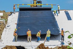
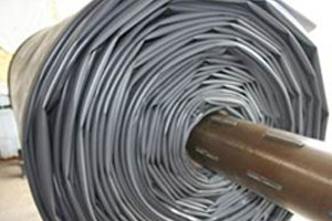
ready for installation
Today, many jurisdictions mandate the use of geomembranes as part of a barrier system for specific applications. For example, in British Columbia, Canada, a landfill barrier system “shall be comprised of a primary High Density Polyethylene (HDPE) geomembrane liner and a secondary compacted clay liner or Geosynthetic Clay Liner (GCL)” (BC MOE 2016). Likewise, in Ontario, Canada, landfills must be lined by a “clayey liner with organic carbon content, in addition to an HDPE geomembrane liner, together with a leachate collection system” (Government of Ontario 2011). In the U.S., the Environmental Protection Agency requires that the bottom and sides of landfills be lined by “two feet of compacted clay soil” overlain by a geomembrane layer to “protect groundwater and the underlying soil from leachate releases” (USEPA 2017).
Leakage through Geomembranes
Geomembranes are not leak-proof as they degrade over time and may be punctured during installation, or by stones in the foundation material. They can also develop stress cracks at wrinkles or folds in the geomembrane following placement of the cover soil or tailings.
The team at the GeoEngineering Centre studied the performance of geomembranes under simulated field conditions typical for TSFs to quantify potential leakage. They found that leakage through holes up to 2 cm in diameter is less than 5 mL/s/km2, which is several orders of magnitude lower than leakage from unlined containment facilities (Joshi, P., pers. comm.). They also found “evidence of an increase in fines in the tailings and underliner in and around the hole” (Rowe et al. 2017).
Professor Rowe and his team performed puncture tests on geomembranes and found that a fine-grained foundation containing isolated stones may cause more geomembrane defects than a packed gravel foundation. They also found that stress cracks occur when there are wrinkles or folds in the geomembrane, when there is differential settlement of the foundation, and when the weight of cover soil or tailings drags the geomembrane down slope.
The colour of a geomembrane can be an important factor in its tendency to wrinkle. Even at moderate temperatures, a black geomembrane can become very hot, making it prone to wrinkling or folding, and in the process losing contact with its foundation. Researchers at the GeoEngineering Centre found that at the same air temperature, white reflective geomembranes can be 21–23°C cooler than black geomembranes, and that white geomembranes are less prone to wrinkling and developing stress cracks (Rentz et al. 2017).
The researchers concluded that damage to geomembranes can be minimized and the potential for leakage reduced by the appropriate selection of geomembranes, proper construction techniques (including adequate construction quality assurance), and by laying the geomembrane over a well-graded smooth foundation, preferably with a protective layer of sand or geotextile (Joshi et al. 2017). Geotextiles are permeable fabrics used for reinforcing slopes and filtering fine-grained material, while allowing water to drain.
Service Life of Geomembranes
The service life of a geomembrane is reached when it no longer adequately contains the material in the containment facility as designed. Its service life depends on its polymer type and additives, its exposure to UV rays, extreme temperatures and chemical reactions, and the potential for puncturing (predominantly by stress cracking).
The key to an effective barrier system is a protective layer between a drainage layer and the geomembrane. The protective layer not only reduces the risk of puncture in the short-term during installation and the initial placement of tailings, but helps to ensure an adequate geomembrane service life (Rowe 2016).
At TSFs, in addition to designing specialized geomembranes for resisting degradation, their degradation may also be reduced by a protective thick layer of tailings with consistently low ground temperatures (McLeod, H., pers. comm.).
A Critical Component of TSF Barrier Systems
By installing geomembranes at TSFs as part of a designed barrier system, mine operators can comply with local environmental regulations by significantly reducing the risk of leakage from TSFs into the environment and improving the recovery and recycling of water from tailings to other mine processing streams.
Ask us how we can help you with your tailings management needs.
For more readings on this topic, refer to the references below:
References
BC Ministry of Environment (BC MOE). 2016. “Landfill Criteria for Municipal Solid Waste.” Accessed June 26, 2017. http://www2.gov.bc.ca/assets/gov/environment/waste-management/garbage/landfill_criteria.pdf.
Ewais, A.M.R., and R.K. Rowe. 2014. “Degradation of 2.4 mm-HDPE geomembrane with high residual HP-OIT,” in 10th International Conference on Geosynthetics (10th ICG), Sept. 21-25, 2014. Berlin, Germany: International Geosynthetics Society.
Government of Ontario. 2011. “O. Reg. 232/98: Landfilling Sites.” Accessed July 24, 2017. https://www.ontario.ca/laws/regulation/980232#BK12.
Joshi, P., R. K. Rowe and R. W. I. Brachman. 2017. “Physical and Hydraulic Response of Geomembrane Wrinkles Underlying Saturated Fine Tailings”. Geosynthetics International. 24(1): 82-94.
Rentz, A.K., R.W.I. Brachman, W.A. Take and R.K. Rowe. 2017. “Comparison of Wrinkles in White and Black HDPE Geomembranes.” Journal of Geotechnical and Geoenvironmental Engineering. 143(8)
Rowe, R.K., P. Joshi, R.W.I. Brachman and H. McLeod. 2017. “Leakage through Holes in Geomembranes below Saturated Tailings.” Journal of Geotechnical and Geoenvironmental Engineering. 143(2)
Rowe, R.K. 2016. “Recent Insights regarding the Design and Construction of Modern MSW Landfills,” in EurAsia 2016 Waste Management Symposium, May 2-4, 2016. Istanbul, Turkey.
United States Environmental Protection Agency (USEPA). 2017. “Municipal Solid Waste Landfills.” Accessed June 21, 2017. https://www.epa.gov/landfills/municipal-solid-waste-landfills.
Guest Author: Ms. Sahar Pakzad, Marketing and Communications Coordinator at Klohn Crippen Berger Ltd.
Acknowledgement: Geotechpedia team would like to thank Ms. Sahar Pakzad, Marketing and Communications Coordinator at KCB Ltd, for sharing this post through Geotechpedia.