Tag Archives: investigation

Geotechnical Risk Management

In our first ever post in Geotechpedia’s blog we tried to answer the most common question among professionals in the Geotechnical engineering industry “Geotechnical Investigation data, always not enough?”. In the specific post, it has been mentioned that “some of us proudly state “I saved so much by reducing the geotechnical investigation” but all this immediately changes when something goes wrong”. We are all aware of how limited or inadequate Geotechnical Investigation (GI) can affect both a project’s schedule and budget. In the following lines, we are trying to quantify these effects, provide guidance on how to easily create a risk scoring matrix and attributed risks, typical geotechnical risks and related mitigation measures.

Cost and time effect

Back in 1748 Benjamin Franklin stated “Time is money” in his “Advice to a Young Tradesman”. This quote finds application in all business sectors and the engineering one couldn’t stand out as an exception. In every project, delays are translated into cost and as such we are going to examine the estimated cost effects of delays deriving from inadequate Geotechnical Investigation on a project’s total construction budget. The most common chart when discussing the risk management in geotechnical engineering is presented below (Figure 1). It is obvious that for low values (1% approximately) of Geotechnical Investigation cost / tender cost (adjusted values), the total increase in construction cost may vary between 2% and 98% with an average value of 15-25%. When the Geotechnical investigation budget is slightly increased (adjusted Geotechnical Investigation cost / construction tender cost values between 2 and 4%) then the total increase in the construction cost drops to a typical range of 2% to 25% with an average value of 5-10%; meaning that an increase of 1-2% on the construction tender cost for additional Geotechnical Investigation signalizes a significant drop of approximately 25 to 50% (absolute values) in the total construction cost.

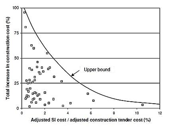
Figure 1: Total increase in construction cost related to adjusted Geotechnical Investigation cost / construction tender cost (source: UK Highways Agency projects (1994))

 Typical Risk Scoring Matrix

During the tendering procedure of a project, a risk assessment needs to be undertaken in order to evaluate the geotechnical risks at an early stage and propose mitigation measures. The following table (Table 1) presents a typical and simple scoring matrix that can be used in this kind of assessments and Table 2 details the specific risks associated with geotechnical works and categorizes them into probability of occurrence and cost/time impact.

The purpose of the following matrix is to help rank the key risks on site.

Table 1 Risk scoring matrix


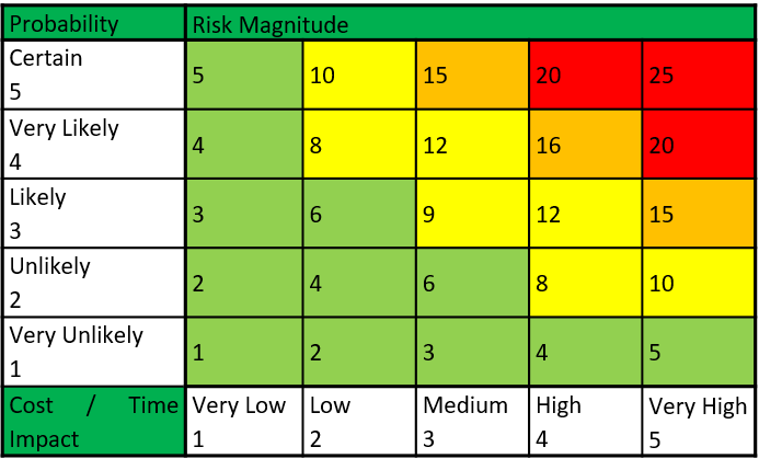
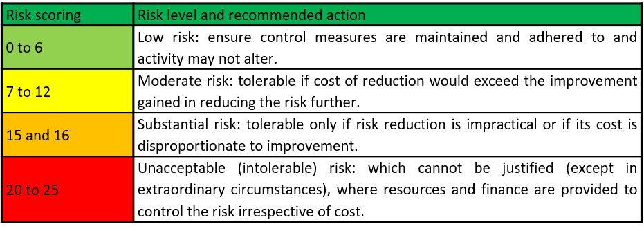
Scores of 1-5 are allocated to the probability and impact in order to quantify and rate the risk rating. The risk scoring matrix should be used in conjunction with the priority action table detailed below (Table 2).

Table 2 Priority action table


Typical Geotechnical Hazards and recommended mitigation measures

Successful implementation of the suggested mitigation measures will assist with managing and reducing known risks to acceptable levels.

Table 3 below presents typical risks/hazards, related impact on construction budget and proposed mitigation measures.

Table 3 Risk/hazard assessment and proposed mitigation measures

In general, Geotechnical Risk Management gains supporters through the Projects Manager’s community since experience has proved that inadequate or incomplete Geotechnical Investigation during the tendering stage can have a severe impact on a project’s schedule and overall cost. Moreover, managing geotechnical risks also helps to increase safety levels in siteworks.

Conclusions

We need to keep in mind that geotechnical risk cannot be avoided and ignored but it can be managed and mitigated.

Taking all the above into consideration it is recommended that a detailed Geotechnical Investigation program is proposed at early stages of each project, following an in-depth desk study of all available information and site walk-over surveys.

It must be highlighted that the above post and its recommendations are to be read in conjunction with site specific available information and with critical thinking. In all cases, the Designer should set strict guidance for adequate Geotechnical Investigation in line with project specifications and international standards.

Useful References

[1] BS5930:1999, British Standard Code of practice for Site Investigations

[2] EuroCode 7 – IS EN 1997-2:1997 (Part 2, Annex B3)

[3] Clayton, C.R.I. (2001) Managing geotechnical risk, Thomas Telford.


Visual observations and field experience versus mathematical formulations and office work

Geotechnical Engineers, Engineering Geologists and Geoprofessionals in general are involved in evaluating and quantifying earth processes, earth materials, and human intervention on or in the earth in a way that can be used to manage geological risk and to produce safe and economical structures such as tunnels, dams, cuts etc.

In order to produce such evaluation the geoprofessional needs to understand the geology of the area, to evaluate the material properties and to analyze the problem at hand based on sound engineering principals.

Unfortunately this does not happen all of the time, either because many are focused in desk studies and numerical models without proper understanding of the actual conditions and others because they oversimplify and base their estimates solely on visual observations of the area.

The problem is that in order to effectively manage and work with models one needs to spend increased amount of time in the office studying the method and learning how to implement in a computer (not much time left for field work!). On the other hand the field is time consuming and usually far away from the office… (not much time to spent in front of a computer!).

Can we combine these two? Many people and consulting offices do, but there are others that don’t.

I will present an example where the lack of field work and understanding scree coreof the situation can produce significant errors. In figure 1 the drilling core of cemented talus is presented. The material is classified as (GP) per ASTM 2487, SPT blow counts produce refusal of penetration and anyone evaluatingscree slope this material from the office would assign the following material properties c’=0kPa and φ’>37ο, and they would design a slope with maximum inclination of about 28o in order to have a FS of about FS>1.4. The reality is that this slope is standing vertical without any stability problems as can be observed in figure 2.

It is very important for geotechnical engineers to have a real understanding of field conditions.

How easy RQD estimations are?

RQD was introduced by D. U. Deere in 1964 for a quantitative description of rock mass. The RQD  is defined as the percent ratio of the sum of core pieces with higher than 10cm length to the total drill run.  Based on the percent or RQD from 0-100% the rock mass quality can be assessed. For example based on the proposal by Deere, rock mass with RQD<25% is characterized as “very poor”. If RQD is higher than 75% it is classified as “Good”.

The RQD estimation is generally easy in the field and has gained a wide popularity. There are issues that should be addressed every time such estimations are made in order to avoid misleading results. In the following some personal experience will be provided regarding this issue.

RQD should not be addressed blindly and only in relation to the length of the core sample for the following reasons:

  1. The diameter of drilling core used should be known and taken into account. In the ISRM Suggested Methods, Brown 1981 a NX (55mm) drill core is mentioned, but in recent years the diameter has significantly increased in many projects and the sample is no more 55mm but can easily be 110mm. The increased diameter has one advantage that better quality core samples can be obtained but at the same time they can include more discontinuities. It is not clear if you will obtain higher or lower RQD values without recognizing the joint system. In the first figure it is observed that the sample with smaller diameter presents more fractures (some may be due to drilling).RQD
  2. The type of drilling barrel is very important. Different quality of drilling can be succeeded with double barrel (which is suggested) or split double core barrel than single or triple core barrel. The triple core and the double split barrel usually produce similar results unless the material is very much fractured. In that case RQD values would be zero anyway.
  3. The driller’s capability may be among the most important aspects especially for rock masses that are fair and poor. In the same location, with the same equipment different drillers may produce different results. Sometimes the artificial fracturing due to drilling may be easily identified but many times they are not especially in certain types of rocks described bellow.
  4. The rock type is extremely important. Geological material wiSiltstone sandstone alteration in a folded structureth foliation and bedding can produce misleading results of natural discontinuities. Clayey like rock materials such as shale, mudstones, siltstones can produce false impressions of discontinuities that are made during drilling but appear to be natural.  In such materials especially when tectonically disturbed, they can appear as solid samples but have discontinuities that are not easily visible.  In such situation RQD estimates have to be used with great caution.
  5. Number of joint sets and orientation, especially orientation can have a profound effect on RQRQDD estimation. For example vertical or near vertical joints may produce 100% RQD in a rock mass that has a discontinuity spacing of just 11cm. This can happen even in horizontal joint sets and a have the following results of RQD=0 for horizontal joint with spacing of 9.9cm and 100% for joint spacing of 10cm!

So when evaluating RQD values,  due consideration should be given to the material type, Driller, drilling equipment, geology and structural features of the rock.