All posts by Chrys Steiakakis

About Chrys Steiakakis

Chrys Steiakakis is a practicing geotechnical engineer with more than fifteen years of experience in the field of geotechnical engineering. He earned his bachelor and master in mining engineering from the Technical University of Crete, Greece and a second master’s degree in Civil Engineering from Virginia Polytechnic Institute and State University, USA. He has been the technical director of engineering department of General Consulting ISTRIA for four years and now he is a partner and also provides his own consultancy services via Geosysta ltd. He has been involved in numerous highway, railway and mining projects. Chrys with his long term collaboration with the Technical University of Crete has participated in numerous research projects in the field of geotechnical engineering and rock mechanics and has provided self sustained seminars of geotechnical engineering in related areas for the Industry. His main field of experience covers all aspects of tunnel design, earthworks design and monitoring (slope stability, embankment in difficult ground, reinforced embankments and retaining walls), landslide investigation and mitigation, foundations for bridges and structures, risk assessment in geotechnical projects and value engineering in large projects.

New era in site investigation data access

Our industry is a bit behind when it comes to new technologies, maybe it is because the scientific progress is moving slowly or not even significantly changing with time. For instance, we’re all still using Terzaghi’s early 1940’s one dimensional consolidation theory or the SPT to conduct our soil investigation. SPT was standardized between 1920 – 1930 and is still in practice today with minor modifications.

We need to explore new technologies in every part of our profession, from site reconnaissance with the use of satellite imagery or drones, to databases for site investigation and monitoring. We need to accept that technology is evolving rapidly and we should adjust and adopt, we need to go forward!

We still prepare site investigation reports in a static manner, we may use software to prepare them but in the end the reports and information they include is limited, without online cross references or procedures to easily update them with new or additional data. Maybe it is time to change?

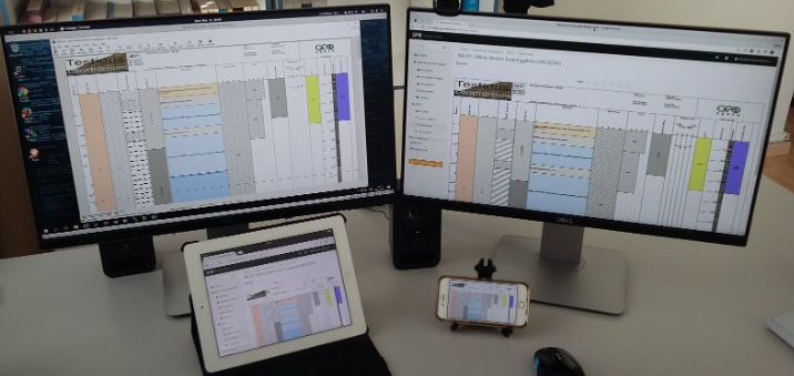
Wouldn’t it be much easier if we could store our site investigation data electronically even from the field?

Wouldn’t be much more efficient if we could correlate different data or data from different locations or from different tests with a click of a button?

Why should we still be buried in thick reports, long sheets of borehole data, difficult to find or correlate and in the end to evaluate them? We are living in the google search era, we are used to type one word or one phrase and expect to have results in a few milliseconds. We should go forward!

It is time that we utilize new and available technology, utilize the power of easily accessed databases, the power of the cloud, being able to have access of our data from anywhere, from our laptop, from our tablet, even from our smartphone.

We need to be able to easily find in our data what we are looking for with a simple search box, just type a drilling name, or view in google maps our investigation area and have a quick look of the locations of our drillings in relations with structures, landforms etc. We need to press one button or tap our finger at the screen and access the information we are looking for. We need to be able to represent investigation data in different formats, for different people and different disciplines. Geologists may want to see information that engineers think is useless. Hydrogeologists may want to view a vast number of water chemical analysis next to the geological description of the ground, this is something that a geotechnical engineer would not appreciate much, he would prefer to see his laboratory index and strength tests. The mining reserve engineer would like to see his ore and mineral percentages. We don’t need to prepare different printed reports or different borehole logs for different disciplines any more.

We can now centrally store all our investigation data and then very easily select what we need to correlate with what or what type of information we want to see next to other information. We can do it from our tablet or smart phone.

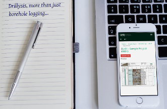
We can be in a meeting and just tap in our smart phone the drilling we want and see any information we have stored in it in a very easy way. This technology is here and we should consider how it will increase our productivity and efficiency.

Evenmore, maybe very useful information could come out when you see different data placed together, which is very hard with printed reports. The geotechnical engineer gets his own format, the hydrogeologist his, this can stop today. Technology is here and we can easily adapt.

Yeager airport landslide

Yeager Airport Expansion slide additional comments

In my previous entry regarding the Yeager airport landslide where I hypothesize for a possible shear zone somewhere near the foundation, I got some interesting comments from fellow engineers. In this entry I would like to clarify some issues.

The hypothesis made about a shear zone was based on published information regarding intercalation of sandstone and shale and photograph observations of the area. A possible dormant landslide was hypothesized by other contributors in the ASCE group in LinkedIn. The model I presented was very simplified in order to test the possibility of the shear surface hypothesis. I will come back to the model with some more details, but I wouldn’t like to deviate from the failure discussion to a model discussion.

I stated previously that usually failures of such large magnitude are more complex and significant data and observations are required to understand the real mechanism. This I am sure will be dealt with by enquiry committees, forensic consultants etc.

I based my hypothesis considering that the Designers of the reinforced earth had done a good job, that the materials used were of appropriate quality and that something outside the structure was responsible or partially responsible for this failure. Many have commented regarding the reinforcement design and all are valuable comments which I will not reply but can be found here. Before a detail analysis and modeling of the failure is possible, additional hard data are required, such as shear strength properties of the actual soil, current tensile strength of the geogrid (as found in the landslide area), excavation at the toe of the slope etc. Until such data become available, only hypothesis can be made that may be completely wrong in the end.

The reason why I made the hypothesis of a shear zone is because it is based on previous information about older landslides in the area, because shale is notoriously tricky material when combined with sandstone and to broaden the possibilities of failure outside the earth structure.

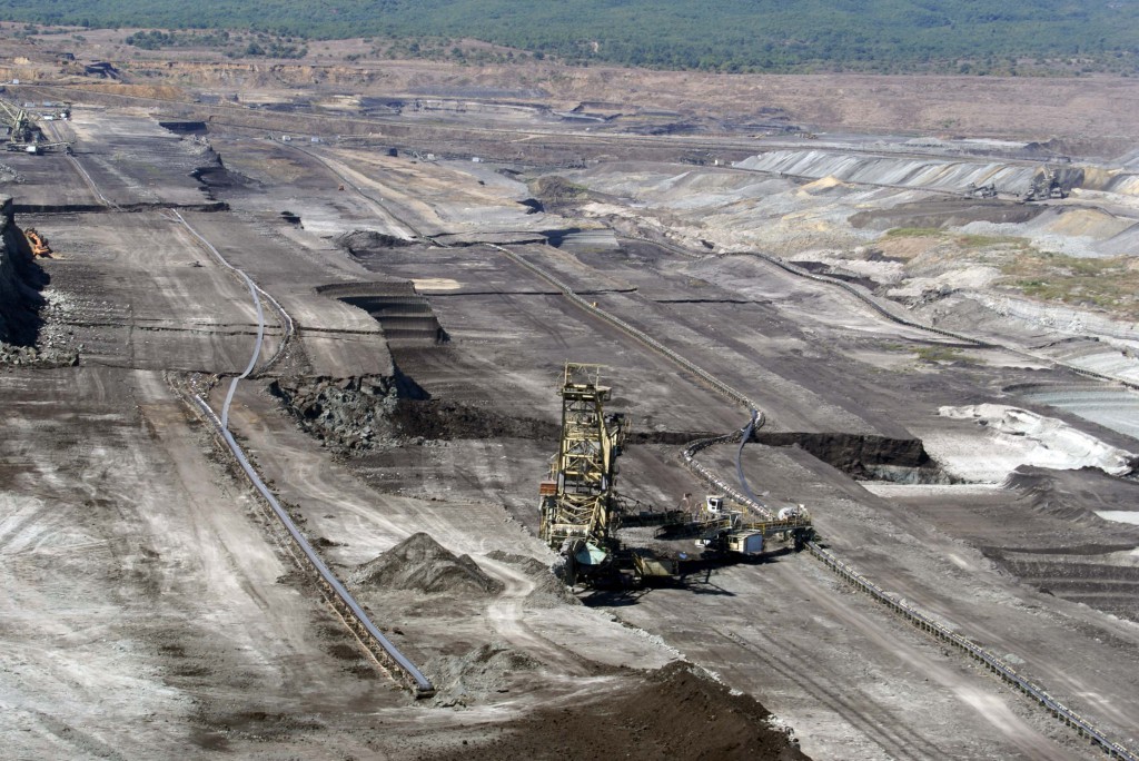
Many times, failures are formed due to very thin weak layers which are very difficult to identify during ground investigation. Sometimes zones (or layers) of a couple of centimeters can be responsible for extended failures. Such zones many times are ignored, especially in very large structures. Consider a borehole of 50-100m with a low strength shale zone of a couple of centimeters, is it always possible to identify it? Even if not ignored, during investigation, a shale zone could appear strong and competent. In the following photograph a translational failure on a lignite mine can be observed. The failure took place on a clayey shale layer of couple of centimeters in a nearly horizontal stratification material. Observe the magnitude of the failure in relation to the huge bucket wheel excavators. Also observe the horizontal movement based on the misalignment of the conveyor belts. The slope inclinations before failure were very shallow, around 1:3 (V:H).

Mine landslide Geotechpedia
Mine landslide

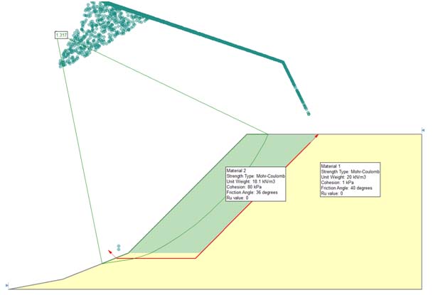
Coming to the slope stability model I used, it was only to validate the possibility of such a failure and not to model the actual reinforced earth slope and its failure. The parameters used were the ones provided by the Lostumbo 2010 presentation and instead of including the reinforcement, a cohesion was used to produce a factor of safety above 1.3 for a circular shear surface inside the soil reinforced structure. A shear surface was not included and a factor of safety above 1.3 was selected because it is assumed that the structure would have been designed above this FS. It is not the intention to assume a soil material with such cohesion. The initial calculation to validate the stability of the model before the failure surface is presented in the following figure.

Slope model
Slope model

But once again I hope the discussion will not deviate from the actual issue and get focused on the model. As R. Peck very elegantly notedstability analyses are tools for the guidance of the investigator. They have their limitations with respect to evaluating the stability of existing dams [the paper was about dam failure] It is not meant that they should never be performed. However, the numerical values for the factor of safety should carry little if any weight in judging the actual safety of the structure with respect to catastrophic failure”. Peck was evaluating a dam failure, and he focused on other issues that play important roles in relation to failures. So in that context I (among others) proposed the lower shear failure or old landslide issue as part of the controlling factors. Hopefully soon we will have many additional hard data to address this issue.

Finally I would like to note that earth retaining structures are a very good solution to many situations and we should not be reluctant to use them because of such incidents. We should though learn about such failures and put all our effort to avoid them in the future.

References:

R. Peck, (1998). “The Place of Stability Calculations in Evaluating the Safety of Existing Embankmnet Dams”, Civil Engineering Practice, Fall 1998.

Yeager failed slope

What could have gone wrong in Yeager Airport Expansion slide?

Yeager airport landslide

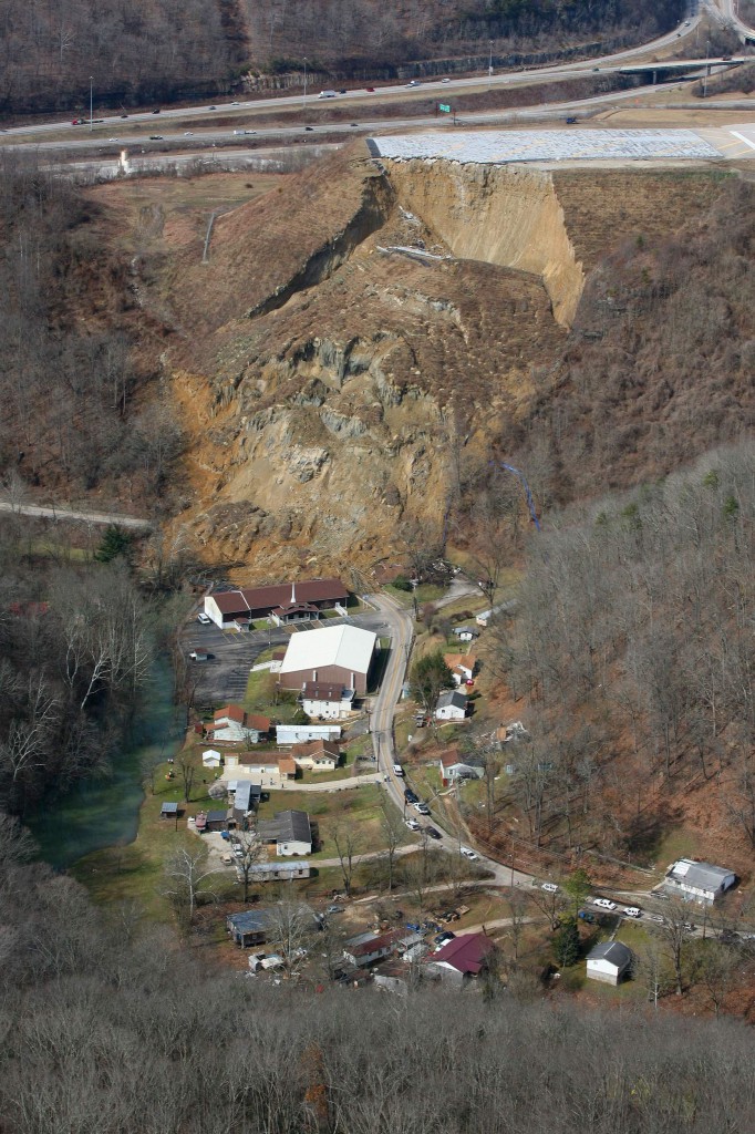
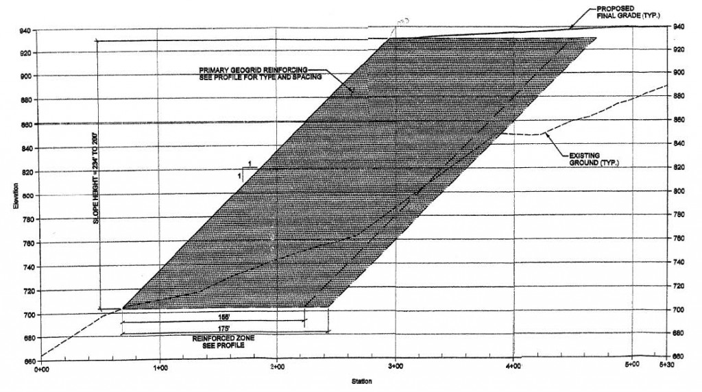
Recent news and photographs present the spectacular slide that occurred in the Yeager Airport Expansion Runway 5. The slide occurred in the South slope which was among the highest if not the highest (~74m) reinforced earth slope in the US. The project had received the award of Excellence – TenCate Geosynthetics in 2007 International Achievement Awards. According to FHWA Manual the Yeager Airport in Charleston WV had been constructed as a massive earthwork in 1940’s. The mountainous conditions around the airport produced steeply dipping slopes to the Elk and Kanawha Rivers. In order to meet FAA Safety Standards runway 5 required a 150m extension in order to create an emergency stopping apron. The most cost effective solution was a 74m high 1H:1V reinforced steepened slope (RSS). The chosen solution is presented in Figure 1 taken from Lostumbo 2010.

2010 STGEC - Yeager Airport - Tallest Reinforced Slope in N America
Figure 1: Reinforced 1:1 earth slope extension of runway 5

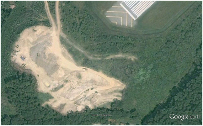
As can be seen from Figure 1, most of the reinforced earth area is above the original ground and only a small part in the slope base is excavated in order to found the reinforced earth structure. Based on Lostumbo, 2010 over 100 borings were performed, with extensive laboratory testing and the final outcome was that the site consisted of primarily fill, colluvial and shallow rock. The material parameters used for the bearing soil zone were unit weight γ=22kN/m3, φ’=40ο and c’=0kPa. I would like to provide some speculations regarding this incident based on the available data found on line and photographs from the news and Google earth. I must point out that these are only speculations since no official data are available to me, nor the exact design or construction plans. These speculations are made just by observations and engineering imagination!   I am sure that significant investigation will take place in the coming months and years which will produce the actual conditions and reasons for this spectacular failure. A picture from Google earth taken on 9/2005 presents the initiation of excavation for the construction of the reinforced earth slope.

Yeager SW slope copy
Figure 2: Google earth image of excavation at Southwest slope of runway 5

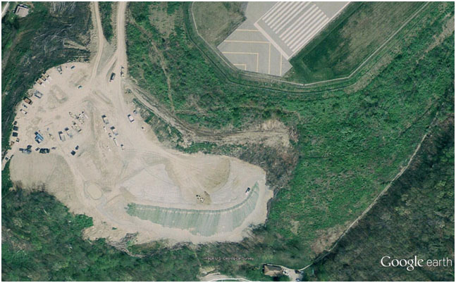
A newer picture taken on 4/2006 presents the progress of works in which a part of the reinforced earth slope has been constructed.

Yeager airport partially constructed slope
Figure 3: Google earth image with partially constructed slope

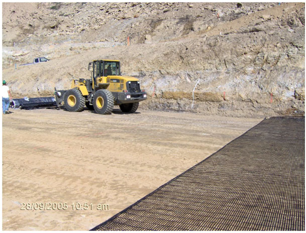
It is very interesting to note that the excavation and foundation of the earth structure did not go all the way to the base of the hill. It is possible that good foundation material (assuming rock) was found in some elevation and was considered appropriate for founding the structure. After all the large earth structure is placed on sound rock (mostly sandstone) with a compressive strength between 30-95MPa! Weathered sandstone from the borrow area had a friction angle between 38.9-39.6o. The placement of the reinforced earth structure on top of bedrock can be observed in figure 4. The bedrock is clearly visible in the back and some moisture can be observed a bit higher in the slope.

Is the “competent” foundation bedrock to blame?, is the design of the reinforced slope to blame? Is the construction practice? Is the intense rainfall? Usually many factors contribute to such a large failure, but at this point with very limited information I would like to focus on the bedrock conditions and the fill material placed on the bedrock.

Yeager airport reinforcement placement
Figure 4: Site photograph shown the placement of reinforcement near the base of the slope, rock formation is clearly visible in the back (Lostumbo 2010).

Is a sound bedrock always appropriate for placing such a large structure? Based on the unconfined compressive strength I would say yes, but are other conditions at play here? Based on Huang et al, 2014the on-site geomorphology consisted of weathered sandstone underlain by sandstone and some shale.” and “The compressive strength of the rock foundation varied from 30MPa to 95MPa. The high bearing capacity of the underlying sandstone foundation and the high friction angle of the onsite weathered sandstone soil meant that the extent of the reinforced slope could be kept to a minimum, and maximum use could be made of the onsite soil.”

Notice the phrase “sandstone and some shale”. Could this simple phrase be the key for what happened? It is well known that even small intercalations of shale can produce enormous geotechnical problems as was the case of Landslide on No.3 Freeway in Taiwan (Duncan, 2013). The first reason is that shale materials have much lower compressive strength but more importantly considerably lower friction angle. Furthermore if not fractured, they present a very low permeability barrier. Usually water is seeping in the sandstone – shale interface, asymmetrically weathers the shale and also produces increased pore pressures in that interface. Could such an interface (or failure surface) had been formed in this case? The answer is, it may be possible and can be seen in the following very simple model in figure 5. (will not go into much detail about the model it is just an example of the possible formation of such a failure surface).

Yeager airport slide model copy
Figure 5: Very simple model evaluating the possibility of failure due to weathered shale intercalation

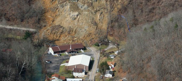
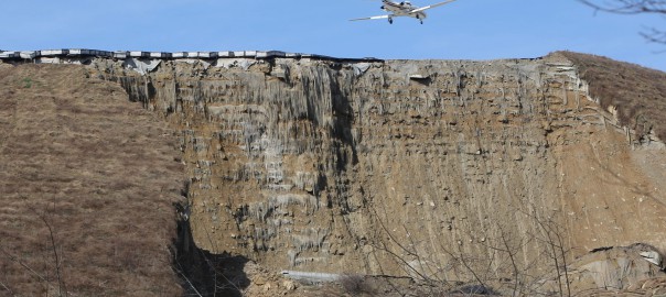
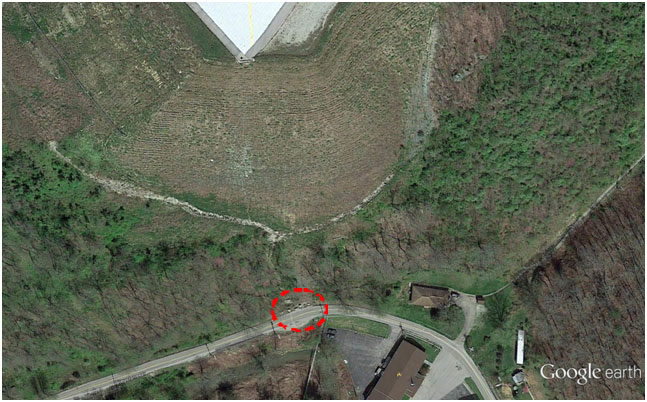
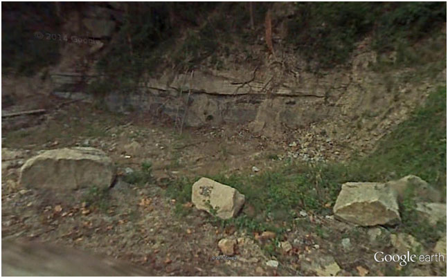
Now let’s go back to actual observations, figure 6 is a Google earth image taken on 3/2012. Please observe the stones between the slope and the road in the red circle. Then let’s go to Google street view in the same location and what we see is shown in figure 7. The layering of the bedrock is clearly visible, furthermore some form of fissure can be observed even with some horizontal movement one can argue based on this image. Could such a feature or a similar one in different elevation be the weakest link of this structure? Could it have been in marginal stability and all it took was some heavy rainfall that increased the pore pressures in this interface and initiated the slide? Food for thought until the actual investigation comes out and the real conditions that lead to instability, which I really hope are much more complex, can be addressed.

Yeager airport google earth 1
Figure 6: Google earth image before the failure, note the rocks between slope and road
Yeager airport toe slope possible failure surface
Figure 7: Google street view in the road just where the rocks are seen. Observe a possible shear surface.

References:

Duncan J. M. (2013). “Impact of time on the performance of reinforced slopes” Geo-Congress 2013.

Huang Z., Al-Saad Q., Nasrazadani S., Wu Felix H. (2014). “Understanding and optimizing the geosynthetic-reinforced steep slopes“, EJGE Vol. 19, 2014

Geotechnical investigation data, always not enough?


IAEG XII congress
IAEG XII congress

This is a very controversial topic in which a straightforward answer is not possible. In this entry I would like to tackle some issues related to our own profession since we are responsiblefor the “acceptable” amount of investigation.

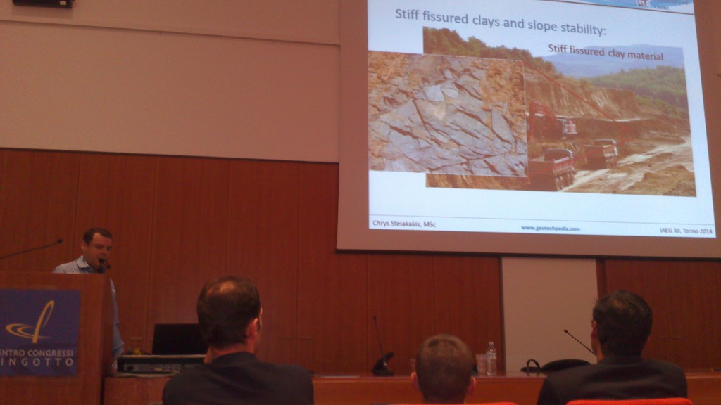
Recently I attended the IAEG 2014 (Engineering Geology) conference in Torino. In this conference numerous interesting topics of engineering geology and geotechnical investigation were covered. It was very interesting to note that in many cases a general conclusion was that not enough geotechnical investigation was executed prior to a geotechnical related failures.DSC_0527 geotechnical investigation


In conversations regarding the site investigation of a project it is very common to hear that “I would like additional investigation but the Client will not provide the funding” or that “the project finance does not allow for more or additional investigation, you have to do with what you have” etc. What do we do in such situations? We do what we have been taught as engineers to do, we overcome the problem. This means that either we accept a larger portion of liability, we either allocate the liability with statements like “additional investigation is warranted during construction” or we design very conservatively or all of the above. In any case, the design is based on limited information and it could go either way.

In many situations, due to the experience of the geotechnical designer or due to very conservative design assumptions no problems are manifested during construction or operation. But sometimes things go terribly wrong and somebody needs to take the blame, leading to long lasting litigations.

Is something wrong with the current practice? Everybody admires the great engineering attitude when nothing goes wrong and with limited investigation the project is completed. Even more, some of us proudly state “I saved so much by reducing the geotechnical investigation” but all this immediately changes when something goes wrong.

Maybe we should start thinking more as doctors? I don’t think anybody has gone with a medical situation and stated to the doctor that “I think you are asking too much medical testing” or “I don’t think an ultrasonic is warranted for my abdominal pain, cant you prescribe some conservative medicine that will make me better without doing all these expensive testing?” I would really like to see the face of the doctor hearing such negotiations. So why are we accepting such negotiations ?

Is geotechnical monitoring important?

The March / April Geo-Strata was almost entirely dedicated to the GAM (Geotechnical Asset Management) for transportation systems. It was very interesting to see how this concept is evolving in the broader field of Geotechnical Engineering and transportation infrastructures.

This Geo-Strata feature is worth reading if you are interested in the future of Asset management in relation to infrastructure projects and geotechnical involvement.

I would like to focus a bit on the issue of geotechnical monitoring. As Thompson et al (GeoStrata, 2014) very elegantly observe, we have all sorts of sensors and warning lights in our cars, which enable both us and the car dealer technicians to identify a future problem as early as possible. If treated early, this problem can be resolved at a minimum cost. If left untreated, however, it could cost us our very life or even other people’s lives should a terrible car accident occur.

Car engine sensors, or airplane sensors or even elevator sensors are mandatory and nobody really argues over whether they should be installed or not. Nobody goes to a car dealership and tries to reduce the vehicle price by arguing that he does not really need the engine sensors because he can visually check his engine once in a while…

Can you imagine an airplane company, saying that in order to reduce operating costs it will remove the black boxes?

So why is it so easy to eliminate geotechnical monitoring instruments from geotechnical projects or so difficult to persuade the owners of the importance of the use of such instruments and information?  I am sure that there is not even a single geotechnical engineer who does not have examples of struggling to enforce the use of some type of

Geotechnical Monitoring

instrument and the client arguing over its cost of installation, cost of operation or even the usefulness of such geotechnical monitoring  and instruments for the project. Even worse this argument is sometimes thrown back at the designers through a challenge such as “why should we monitor the wall? Haven’t you designed it to be safe?”

Airlines and government boards do not consider installing black boxes only in planes that are old and with mechanical problems that may have a high risk of falling out of the sky. Imagine if such practices were taking place, would our planes be as safe as they are? Would they have evolved in the way they have?

Why is it so hard to do the same in geotechnical projects? Why is geotechnical monitoring and instrument installation, warranted in critical situations, on critical structures but not on ordinary slopes or embankments etc? How is the profession going to excel in future projects when real behavior of geo-structures is so difficult to find and evaluate?

As a profession, we should try to persuade owners, government officials, policy makers etc of the significance of reliable geotechnical monitoring systems included in the majority of geotechnical works. By doing this  future works and infrastructure will become safer and costs will fall far more than we may realize. Don’t put a price tag in current projects without considering future projects…

Development of Rock Engineering and updating EC7

Every geotechnical engineer knows E. Hoek and his significant contribution to rock mechanics. Here you can find his first on line lecture titled “The Development of Rock Engineering”, you just need to enter your name, e-mail and company and you get the password to view the on line lecture.

This lecture provides interesting historical background regarding the development of rock mechanics  and the future trends of the profession.

Another interesting PowerPoint presentation regarding the future direction of Eurocode 7 published by Dr Andrew Bond of Geocentrix is worth reading. In this presentation the Quo Vadis of Eurocode 7, the proposed changes and modifications are presented.

Geotechnical engineering standard of care

November – December issue of Geo-Strata which is a published forum of the Geo-Institute of the American Society of Civil Engineers (ASCE) featured an article by Patrick C. Lucia, Chairman Emeritus of Geosyntec Consultants, titled “As I See It: Geotechnical Forensic Engineering in Defense of Geotechnical Engineers”.
In the article Patrick shares his over 25 years of experience in forensic geotechnical investigation of failures and the compliance of Geotechnical Engineers to “Standard of Care”. In his opinion the majority of failures occur due to “lack of process in conducting the geotechnical engineering practice”.


Unfortunately it is very difficult to standardize geotechnical engineering practice in a way that other engineering disciplines have. The difficulty of standardizing geotechnical practice is that ground is not standard. This is why geotechnical engineering is so challenging. How can you standardize an investigation in a new project? Is the text book “influence zone” depth an adequate depth to drill? Can a few centimeters thick unfavorable clay seam be found with two 30m borings in a proposed cut? Can an undisturbed or even remolded sample be acquired from that seam? Can we pursue the client to spend additional thousands of dollars when we are unsure of what lies beneath?
Pat is arguing that “when the process of engineering is properly done and properly documented, it will far reduce the number of claims and make the defense of those claims much easier.” This is true but maybe difficult, especially in a world of fast track projects and low bids. Maybe our profession needs to do much more to “standardize” proper engineering process. Firms may need to take action to “educate” potential clients and owners about the importance of a sound geotechnical investigation, peer reviewed process in ground properties evaluation and design and necessary time that is needed.
Time is a fundamental problem in geotechnical engineering profession. It is not easily understood why maybe a month is needed for a simple foundation investigation. How can you argue when you hear “we do not have such time, we need the results in a week!”, as if we control the permeability characteristics of a clay in a consolidation test!!!
These and many other issues make our profession so challenging, difficult but at the same time so rewarding, from a scientific point of view (I don’t know any billionaire geotechnical engineer). We need to practice geotechnical engineering and at the same time educate the rest of involved disciplines in its difficulties. Unfortunately probably we are not doing very well in the second part of educating…

Geosysta welcomes 2014

Geotechpedia 2014

Geotechpedia enters 2014 with the ambition to provide more geotechnical information and contribute to the geosociety with interesting and valuable publication links, software from the industry and equipment used in the sector.

Geotechpedia now has an updated look and feel more appropriate for today’s web. We hope we can make your experience more efficient and pleasurable at the same time while we save you precious time when searching for geotechnical information.


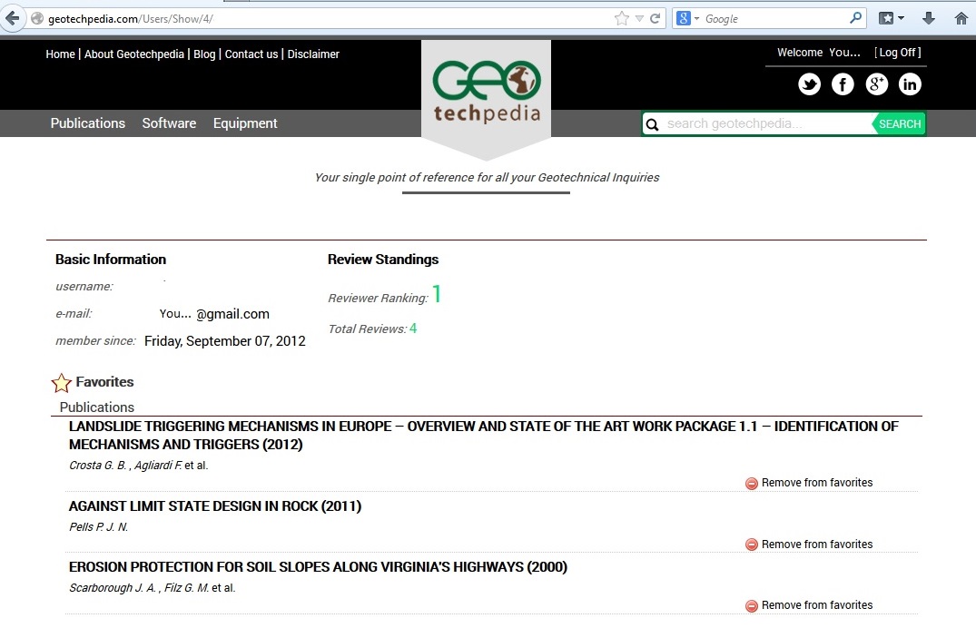
Register with Geotechpedia, and become a member of it’s online geotechnical community. It is very easy and safe, since it uses open ID. Geotechpedia does not request that you create yet one more password and will not store any.


By Registering you can rate all geotechnical information items provided in the site, you can review papers, software or equipment and you can add items in your favorite section.

Geotechpedia registered users page

Help others with your knowledge to get faster incite in our provided geotechnical information. Access your favorite items, review etc just by clicking on your user name in the top of the page

Geotechpedia and Geosysta wish you all a happy and productive new year.

Geosysta welcomes 2014

How much does a geotechnical design cost?

I am sure that many geotechnical designers have either been asked this question or have had to answer it internally in order to price a project. After the offer has been prepared, comes the negotiation phase, where the owner of the project starts asking questions about the “high” price (in his opinion) or about a different offer he has had which was half that price!
I would like to point out some aspects that come into play in this negotiating tango between the Consultant and the Owner and some pitfalls that can come about with relation to this issue.
In geotechnical engineering a design is never “easy” or “simple” and this is because the ground is inherently variable, anisotropic and with minor details that cannot be easily assessed but nevertheless can have a detrimental effect during construction. Do we forget this, many times in our practice?
Pizza
So how do you go about performing a geotechnical design? A geotechnical investigation is executed initially with a predefined number of boreholes, usually less than we would like and a selective number of field and laboratory tests are executed. This investigation may be based on prior experience of the area but often it is not. The depth and location are governed with minimum information and mostly based on the structure to be constructed. Then with the geotechnical information gathered and evaluated the subsurface is formulated and the geotechnical design is executed, based on some form of standard (Eurocode, LRFD etc).
So the question now becomes “how many man hours will your engineers work determining the price you will ask for?” So in an effort to reduce the cost of design, the limited geotechnical investigation parameters are used with some partial factors of safety and the calculations are executed with nice software for bearing capacity or slope stability etc and the design is completed, on time, satisfying the standards and everybody is comfortable over the outcome. So how many man hours does such a procedure require? Don’t you think you should reduce your offer?
This is a recipe for disaster. In order to cut the cost of design, many things that should have been evaluated are not, inexperienced engineers work in the office with the software that they know so well but at the same time they may completely lose touch with the actual conditions or the geotechnical details that will actually control the performance of the project.
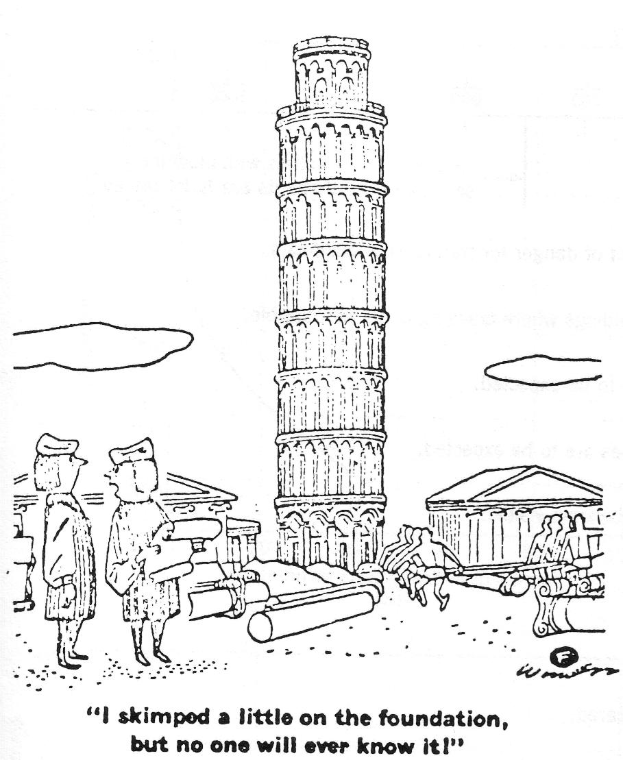
The cost of performing a geotechnical design is not merely the man hours spent doing some mainstream calculations but the time and experience that has been devoted to evaluate the most probable conditions and the most unfavorable conceivable deviations from these conditions and how they will affect the proposed project. This is not an easy task; it needs great experience (shouldn’t this be paid?) and many hours of thinking, sketching, performing simple hand or computer calculations, revisiting the site and the site investigation information etc. But this cannot be easily measured or quantified and produced as a cost estimate. So how can two Consultants compete when one routinely executes such practices and the other doesn’t? Sometimes luck favors the bold so the second consultant could have the same track record as the first one. And if a failure or excessive deformation etc happens then it is easy to blame it on “the unforeseen geological conditions”. No harm done! Just the budget and time of the project may significantly increase, maybe increase orders of magnitude in relation to the reduction that was achieved with the negotiation of the geotechnical design fees or with the selection of the geotechnical consultant with the lowest bid.

Factor of safety and probability of failure, E. Hoek  - Practical Rock Slope Engineering
So Geotechnical Designers should advertise in more detail what they actually do, advertise the experience and expertise they pose in house and the way they tackle a geotechnical design. They may need to make the owner aware of what is at stake with an improper geotechnical design even if it meets all available standards.

Owners should take a step back and think; is the lower bid the best way to go? Is the reduced price that was achieved after hours of negotiations worth the risk of an improper geotechnical design? What is the gain of a reduced cost of design in relation to the actual cost of construction? Never forget that you get what you pay for and this in geotechnical design can really have a significant cost!

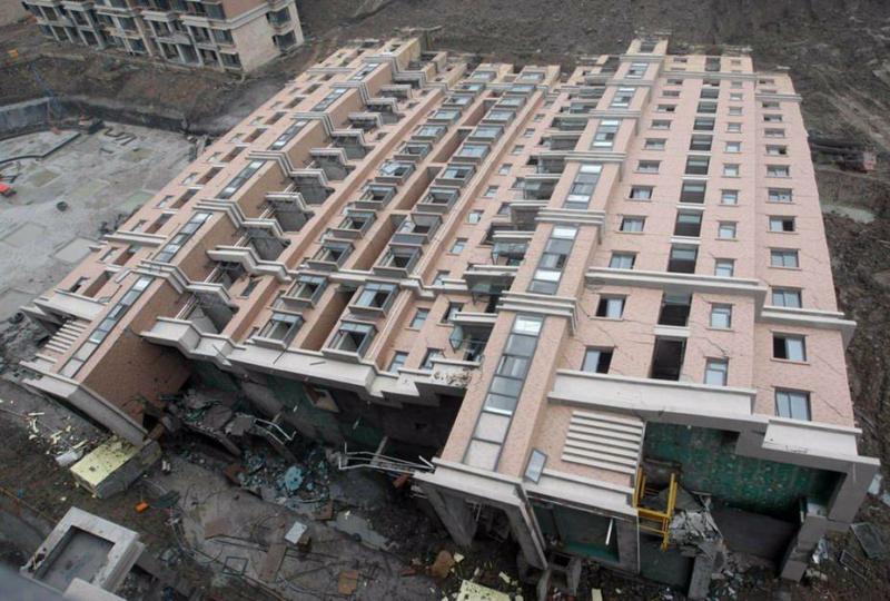
Shanghai building foundation failure, http://activerain.com/blogsview/1524118/nashville-building-inspection-foundation-failure-what-is-wrong-with-this-picture-3-2-10

NATM is it New, Austrian or a Method?

NATM or New Austrian Tunneling Method has been for long time under scrutiny. Many disagree that was “NEW” in 1957 (Kovari 2003, Jaeger 1979) when it was introduced by L. von Rabcewicz. Many more have disagreed with the term “METHOD” such as Kovari 1993.

The term “NEW” was introduced by Rabcewicz to distinguish what he was proposing in relation to the current at that time “old” way tunnels were built, which was mostly with steel and wood lagging or/and brick arching.

For example in figure 1 the support method “mining and timbering method” is shown. This method was used for New York tunnel extension of the Pennsylvania railroad named the East River Tunnel. This tunnel was constructed between 1904 and 1909. As can be seen heavy timbering was utilized to support the crown which is excavated sequentially but due to the heavy and condensed timbering, space is limited.

Fig.1: New York tunnel extension of the Pennsylvania railroad (Gutenberg EBook )

For the same project in locations of soft rock or in general soft ground the following support method was used as described: “Where the rock was penetrated and soft ground showed in the roof, poling boards were driven ahead over the crown-bars”.

Fig.2: New York tunnel extension of the Pennsylvania railroad (Gutenberg EBook )

The Wislon Tunnel, Honolulu was excavated around 1954 and the “American support method” was used in which “two vertical slots, one each side of the tunnel, into which the next set of vertical posts could be placed.” Excavation advance step was around 1.2-1.5m. Due to the nature of the material a “progressive sloughing or spalling caused the upper part of the face to assume a more nearly veridical slope” also in some areas dome shaped over break was formed which was packed with timber as can be seen in figure 3 (Peck, 1981).

Fig. 3: Wislon Tunnel, Honolulu (Peck 1981)

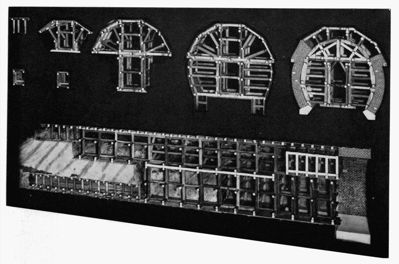
In the next figure the successive steps of the “old” Austrian tunneling or “old” tunneling method can be seen. The support of the tunnel is made initially by densely packed timbering and then a final lining composed of a thick brick wall is constructed.

Fig. 4: The successive states in the enlargement of a mid-19th century railroad tunnel, using the Austrian system of timbering (Smithsonian Institution United States National Museum Bulletin 240).

The term “NEW” was used to distinguish from the “old” or traditional way of excavating and supporting tunnels. Kovari, 2003 provides a thorough literature review regarding the use of rock bolts, shotcrete, steel ribs and the combination of these methods. In his paper provides historical literature regarding the use of all these support methods way before Rebcewicz proposed the “NEW” way of tunneling. For example he mentions about a rock bolt procedure published in 1919 with a subtitle “Mine drift support with iron anchors”. Also in his opinion a major advance in rock bolting and shotcrete was made at the 42km Delaware Water Supply Aqueduct in New York in which “…instead of the usual steel ribs (Nolan, 1952). On November 8, 1950 permission was given to the contractor with several conditions. Among them were the application of steel roof ties (channels bolted to the rock) and gunite the rock as soon as possible after bolts and plates are put in place” (Kovari, 2003).

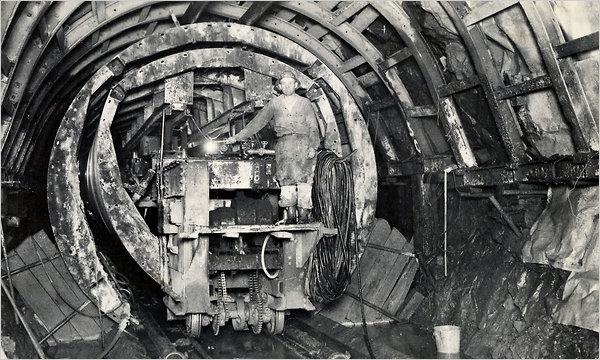
Fig 6. Working on the Rondout-West Branch Tunnel of the Delaware Aqueduct in 1942. Cracks have caused flooding in Wawarsing, N.Y., in Ulster County.

Prof. Jaeger states that the analysis in which the rock and support interact provided by Maillart (1922, 1923) and Andrea (1926, 1961) “…is more realistic than Rabcewicz’s approach [and] could have led to an early discovery of the NATM. It did not.”

Rabcewicz promoted a “NEW” way of tunnel support in which “using shotcrete and rockbolts (Austrian patent 1956) [could] cut time and problems considerably” (Jaeger, 1979). So was this actually a “NEW” method at that time? Does it really matter? Was Facebook the first social media network? No, but probably due to better marketing or better programming or some other details, became the first choice. Probably it was the same way with NATM, better marketing? Better detailed approach? Better specifications? Nobody exactly knows, but one thing is for sure, today when rock support with shotcrete – rockbolts and steel sets is proposed, immediately NATM comes to mind.

Criticism continues in relation to the term “METHOD” and especially that the surrounding rock becomes a load bearing element. In 1980 the Austrian National Committee on Underground Construction published the following statement:

“The New Austrian Tunnelling Method (NATM) is based on a concept whereby the ground (rock or soil) surrounding an underground opening becomes a load bearing structural component through activation of a ring – like body of supporting ground”.

The critic of such a statement describing a method of utilizing the ground as rock bearing element is not unique to NATM but it is the norm for all tunnel support systems even the “old” ones.

It is very interesting to note that the idea that the ground is the major load bearing element was understood as early as 1922 by Maillart from the experience gained from the Simplon tunnel with well over 2000m of overburden constructed in the Alps.

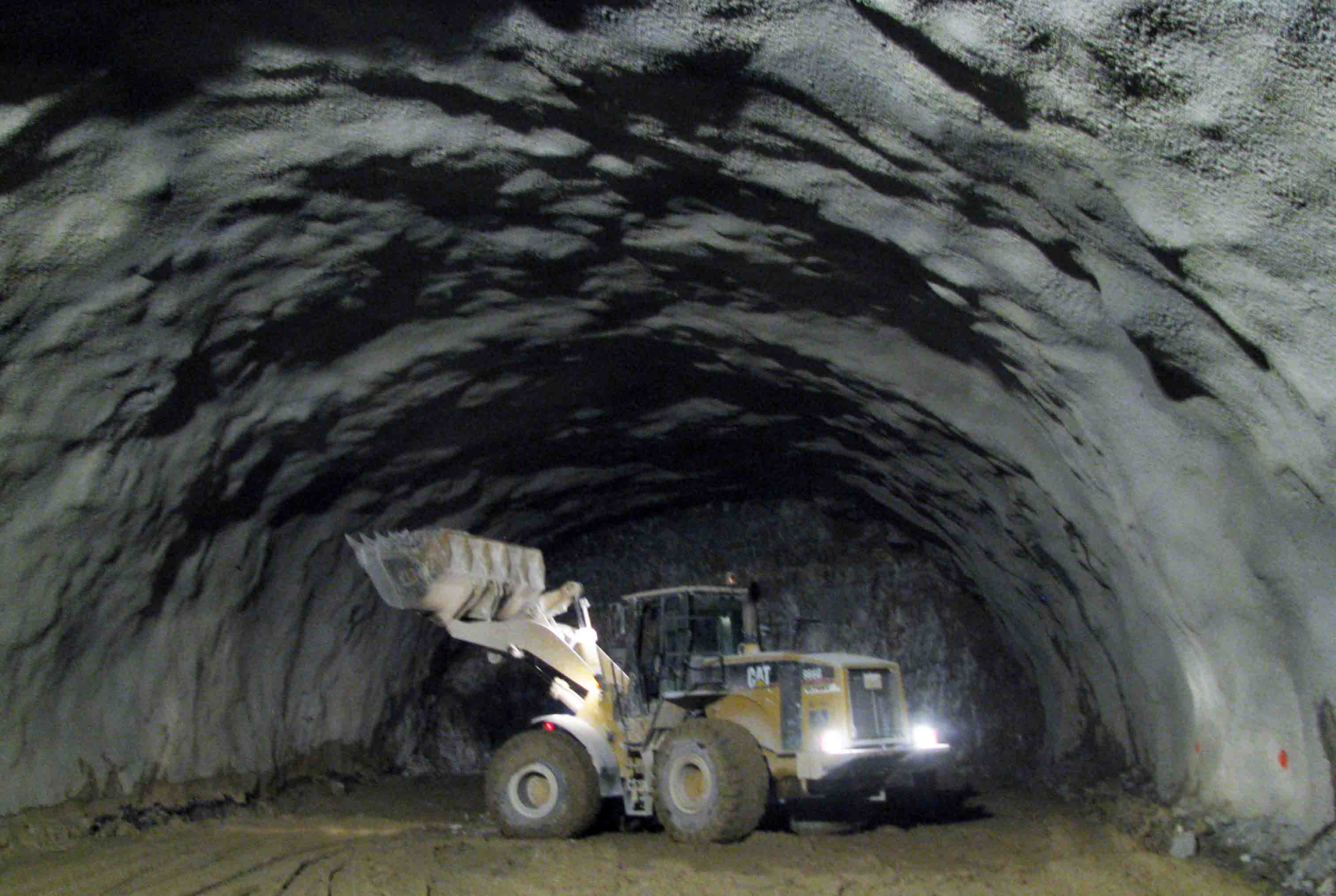
It is possible that the statement: “ground surrounding an underground opening becomes a load bearing structural component..” was another marketing trick. People working underground need to feel safe! The “stronger” the support the safer the miners feel. But what is a “strong” support? It is easily understood that a densely packed timber support shown in Figure 1, 3, 4 and 5 can provide a much better sociological effect than 10 rock bolts and a thin 20cm shell of shotcrete (fig 7).

Fig. 7: Shotcrete and bolts for tunnel excavation with NATM

Even today the psychological effect is very important. Many times mines may chose thick steel ribs (HEB200) every 1.0m spacing considering that it is safer than let’s say 20cm of shotcrete with lattice girders.

It is possible that the “load bearing ground ring” which is utilized in one way or another in any underground opening was baptized as the “METHOD” in NATM in order to make miners “feel” safer with this “light” support. Any other explanation could be possible but the fact is that every underground opening has to utilize the ground as a load bearing element and not only if NATM is used.

It can be said that NATM was neither “NEW” neither of “AUSTRIAN” origin or a “METHOD” but at the same time a great respect is deserved to the Austrian Engineers and Miners that promoted this type of support that has since utilized all over the world.

Comments are welcomed.

Here is an interesting forum on the topic. Visit Underground Geomechanics Group in LinkedIn for interesting discussions.

References:

  1. Brace J. H., Mason F.  and Woodarm S. H., (1910). “The New York tunnel extension of the Pennsylvania railroad. The East River Tunnels”, The Project Gutenberg EBook of Transactions of the American Society of Civil Engineers, vol. LXVIII
  2. Hewett B. H. M. and Brown W. L. (1910). “The New York tunnel extension of the Pennsylvania railroad. The East River Tunnels, Paper No. 1159”. The Project Gutenberg EBook of Transactions of the American Society of Civil Engineers, vol. LXVIII
  3. Jaeger C., (1979). “Rock mechanics and engineering”, Second Edition, Cambridge University Press.
  4. Kovari K., (1993). “Erroneous Concepts behind NATM”, Lecture given at the Rabcewicz-Geomechanical Colloquium in Salzburg, Octobre 14, 1993.
  5. Kovari K., (2003). “History of the sprayed concrete lining method – part II: milestones  up to the 1960s”, Tunnelling and Underground Space Technology 18.
  6. Peck R. (1981). Soft ground tunneling, Balkema