Proposal for estimated Earth Pressures on Cut and Cover Sidewall in rock cuts
A common design issue many Geotechnical Engineers have come across in their career is the estimation of earth pressures on a Cut and Cover (C&C) sidewall located close to a rock cut. Usually, a C&C structure is designed and constructed close to an open excavation slope (supported or not) and then covered over with backfill material when construction of the structure is complete.
The specific course discusses a theoretical design case of a C&C in a stable rock cut and how the lateral earth pressures on the structure’s sidewall could be estimated.
Theoretical background on lateral earth pressures [1]
Active and passive earth pressures are the two stages of stress in soils which are of particular interest in the design or analysis of shoring systems. Active pressure is the limiting condition in which the earth exerts an outwards force stress on a retaining system and the members tend to move towards the excavation. Passive pressure is a limiting condition in which the retaining system exerts a stress on the soil with displacements towards the soil. Since soils have a greater passive resistance, the earth pressures are not the same for active and passive conditions. When a state of soil failure has been reached, active and passive failure zones, approximated by straight planes, will develop as shown in the following figure (level surfaces depicted) but at different displacements.
Figure 1: Limiting active and passive failure zones at different displacements
Two common earth pressure theories are:
-The Coulomb theory which provides a method of analysis that gives the resultant horizontal force on a retaining system for any slope of wall, wall friction, and slope of backfill provided. This theory is based on the assumption that soil shear resistance develops along a failure plane in the soil mass.
The wall friction angle (δ) value is always less than the internal angle of shear resistance (φ) one. It is common practice to assume a wall friction angle value of δ = 1/3 (φ) to 2/3 (φ). It must be noted that as wall friction increases, lateral earth pressured decrease.
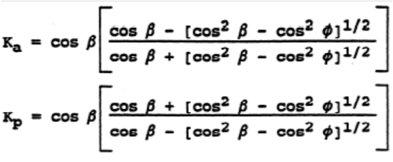
-The Rankine theory which assumes that there is no wall friction and the ground and failure surfaces are straight planes, and that the resultant force acts parallel to the backfill slope (i.e., no friction acting between the soil and the backfill). The coefficients according to Rankine’s theory are given by the following expressions:
If the backslope of the embankment behind the wall is level (i.e., b = 0) the equations are simplified as follows:
The above theories calculate earth pressures when an “infinite”soil mass exist behind the retaining system, but is this pressure the same when limited soil backfill is placed behind the retaining system? Such a case can be found in stable rock cuts with limited excavation behind the retaining wall.
Design Assumptions
As stated above, during the design stage of a C&C structure, the Geotechnical Engineer is commonly requested to provide the Structural Engineer with the estimated (active) earth pressures on the structure’s sidewall due to the backfill.
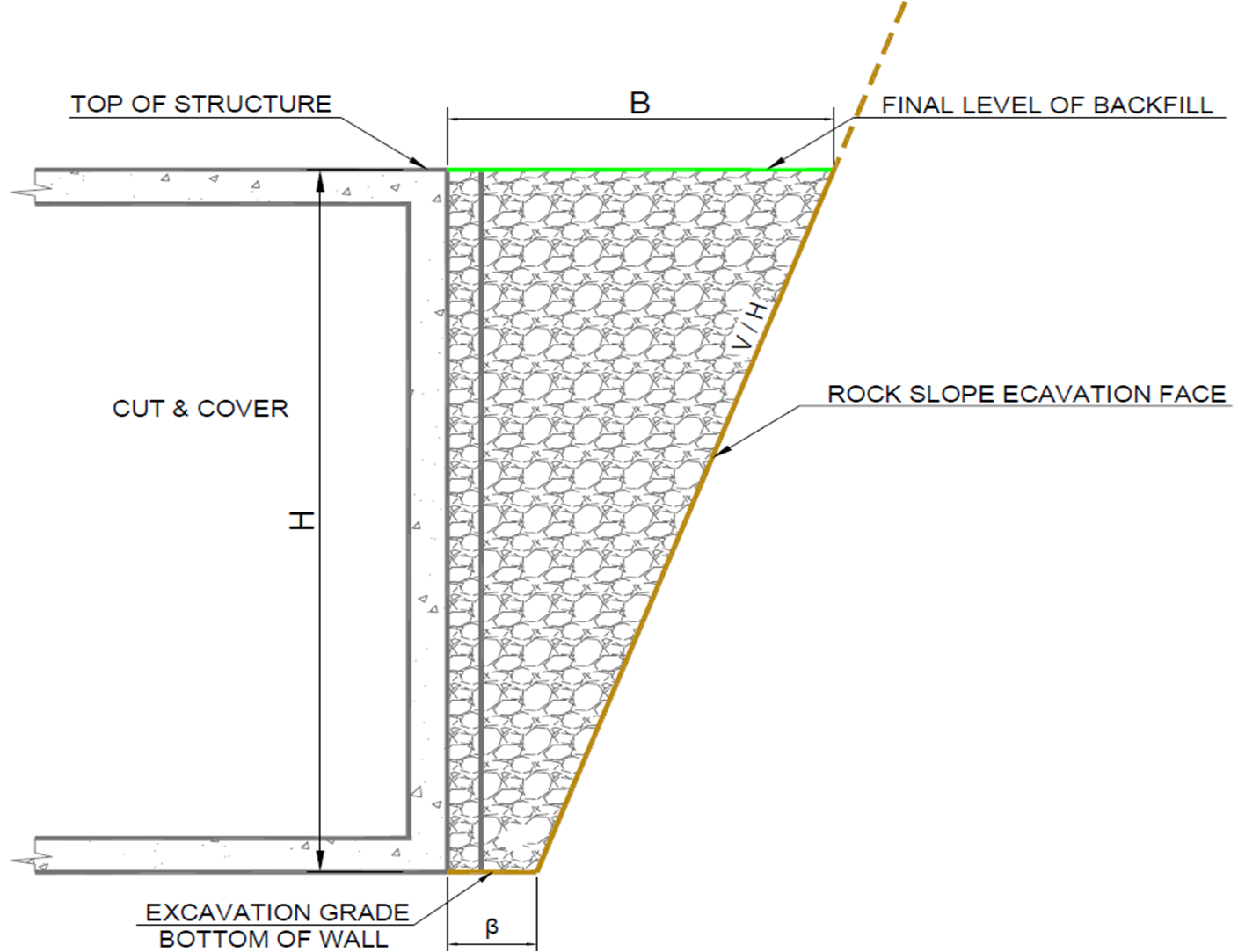
A typical cross section of a highway C&C which will be studied is presented in Figure 2, below. The geometry and geotechnical properties of the backfill area are given in Tables 1 and 2, respectively.
Figure 2: Typical cross section of a Cut & Cover at the backfill area
Table 1: Backfill geometry
Table 2: Backfill geotechnical properties
The geotechnical calculations are conducted under the assumption that the active earth pressures exerted on the sidewall derive only from the backfill material since it is considered that a stable rock cut or an in situ permanent soil nail reinforced wall exist, consequently, the corresponding slope earth pressures would be practically zero.
The interface friction angle between the backfill material and the sidewall was taken conservatively equal to zero based on the assumption that Expanded Polystyrene (EPS) will be applied on the sidewall.
Design calculations
Based on Coulomb’s theory, the forces acting on the C&C sidewall were the ones described below and presented in Figures 3 and 4.
-The backfill self weight (W). It must be noted that the self weight of the backfill material to be placed above the C&C roof slab was also taken into account.
-The resultant force (F) acting on the failure surface. The two components of that force are the normal force (N) and the friction (T). It must be noted that the sliding surface was considered cohesionless (c=0 kPa).
-The active earth pressure (Ρα) acting on the sidewall. Due to the presence of the EPS as described above, the resultant active earth pressure was considered acting normally on the sidewall.
-In the seismic design case, the normal inertia forces (normal and horizontal) of the backfill.
Figure 3: Forces acting on the C&C sidewall under static conditions
Figure 4: Forces acting on the C&C sidewall under seismic conditions
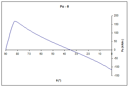
Due to the geometry of the backfill area and the aforementioned assumptions, the active earth pressures couldn’t be calculated under the assumption of a failure plane at 45°-φ/2. For that reason, a generic spreadsheet was produced for calculating the earth pressures for each straight failure plane.
The results in the form of charts are presented in the following Figures 5 and 6. Detailed input and output are shown in Figures 7 and 8.
Figure 5: Active earth pressures per angle of failure plane diagram under static conditions
Figure 6: Active earth pressures per angle of failure plane diagram under seismic conditions
 Figure 7: Active earth pressures per angle of failure plane diagram under static conditions
 Figure 8: Active earth pressures per angle of failure plane diagram under seismic conditions
If the backfill geometry isn’t taken into consideration and Rankine’s theory has been followed blindly, assuming that the failure plane would be at 45°-φ/2, a critical angle of θcr = 27,5° would have been calculated with a resultant pressure of Pa = 1/2xkaxγxH2 = 333,9kPa (static conditions). That means that the estimated earth pressures would be almost twice (100%) the probable ones leading to overdesign.
Conclusions-Recommendations
The estimation of lateral earth pressures on structures is a common problem in geotechnical engineering, especially in the case of complex geometries defined by other geotechnical designs (usually stabilization measures) in close proximity.
The specific note presented a theoretical design case where the estimation of active earth pressures and their magnitude following Rankine’s theory on a C&C sidewall couldn’t be established due to backfill complex geometry. A spreadsheet has been elaborated for design purposes in order to estimate, through repeated iterations, the critical angle of failure plane for which the maximum earth pressures on the structure occurred. The backfill material is considered to be of cohesionless nature without creeping phenomena.
There is never a rule of thumb and empirical approaches should be followed with engineering judgement since each design is unique and must always be treated as such.
It must be highlighted that the above note and its recommendations are to be read in conjunction with site specific available information and engineering judgement must be implemented in all design stages. Monitoring of earth pressures in such situations could enlighten more the theoretical approaches.
The views expressed in this note are only informative and should be used with great care in design situations.
References
[1] Steven F. Bartlett (2010), Examples of Retaining Walls. Earth Pressure Theory.


