Category Archives: Tunnel Support

Geosysta at Klokova Tunnel Breakthrough (photos and videos)

A major milestone at Klokova tunnel has been reached on June 23rd, as part of IONIA Odos Motorway overall progress, with the breakthrough of the twin tunnel right branch (length: 2,900m approximately).

TERNA S.A. engineers tunneled through the final few meters connecting the two segments of the right branch on Thursday afternoon (23/06/2016), after less than 2-years since mobilisation which is considered a major achievement taking into account the difficulties met at several areas.

Geosysta Ltd, as part of the design team of the Austrian iC Consulenten ZT GesmbH, are responsible for the primary and final support of the Klokova tunnel, were invited to eye witness the breakthrough and be part of this milestone achievement.

We just couldn’t miss that…!

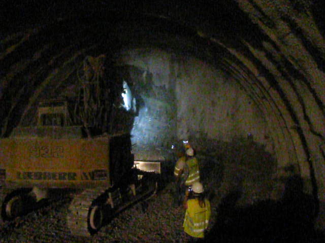
Initially, the rockmass was loosened with the use of explosives and afterwards, with the simultaneous use of two hydraulic hammers, TERNA people managed to bring down the final thin layer of bedrock standing between the two tunnel sides.

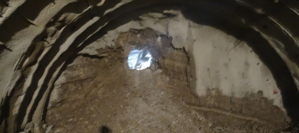
Seconds after blasting
Fig. 1: Seconds after blasting
Fig. 2: Tunnel back face after blasting

Watch the moment of the breakthrough from two different angles below.

MVI_4907

Klokova tunnel breakthrough

Fig. 3: Tunnel breakthrough
Fig. 4: Tunnel breakthrough
Fig. 5: Geosysta and iC personnel celebrating with TERNA personnel (from left to right) Georgia Papavgeri, Alexander Athanassiou, Chrysanthos Steiakakis

IONIA ODOS

IONIA ODOS will be connecting the entire Western Greece starting at Ioannina and following the western coastline of mainland Greece down to the Gulf of Corinth. At Rio, it crosses the gulf via the Rio-Antirrio Bridge. The new motorway is currently under construction and includes:

  • 196 km of a new, modern and high-standards motorway
  • 4 bidirectional tunnels of a total length of 11,2 km
  • 24 bridges of a total length of 7 km
  • 77 underpasses and 24 overpasses
(source: www.neaodos.gr/)

KLOKOVA TUNNELS

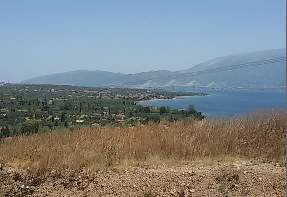
Klokova tunnel is located in the south-west of Aitolia- Akarnania region in Greece and, more specifically, at a distance of about 7km from the Rio-Antirrio Bridge. The current national highway alignment runs along the south outskirts of Klokova mountain.

Fig. 6: Wider area of project’s location (SW Greece / Aitolia – Akarnania)
Fig. 7: Existing national highway alignment along Klokova mountain outskirts
ScreenShot3
Fig. 8: View of the Rio-Antirrio bridge from the Klokova tunnel entry portal

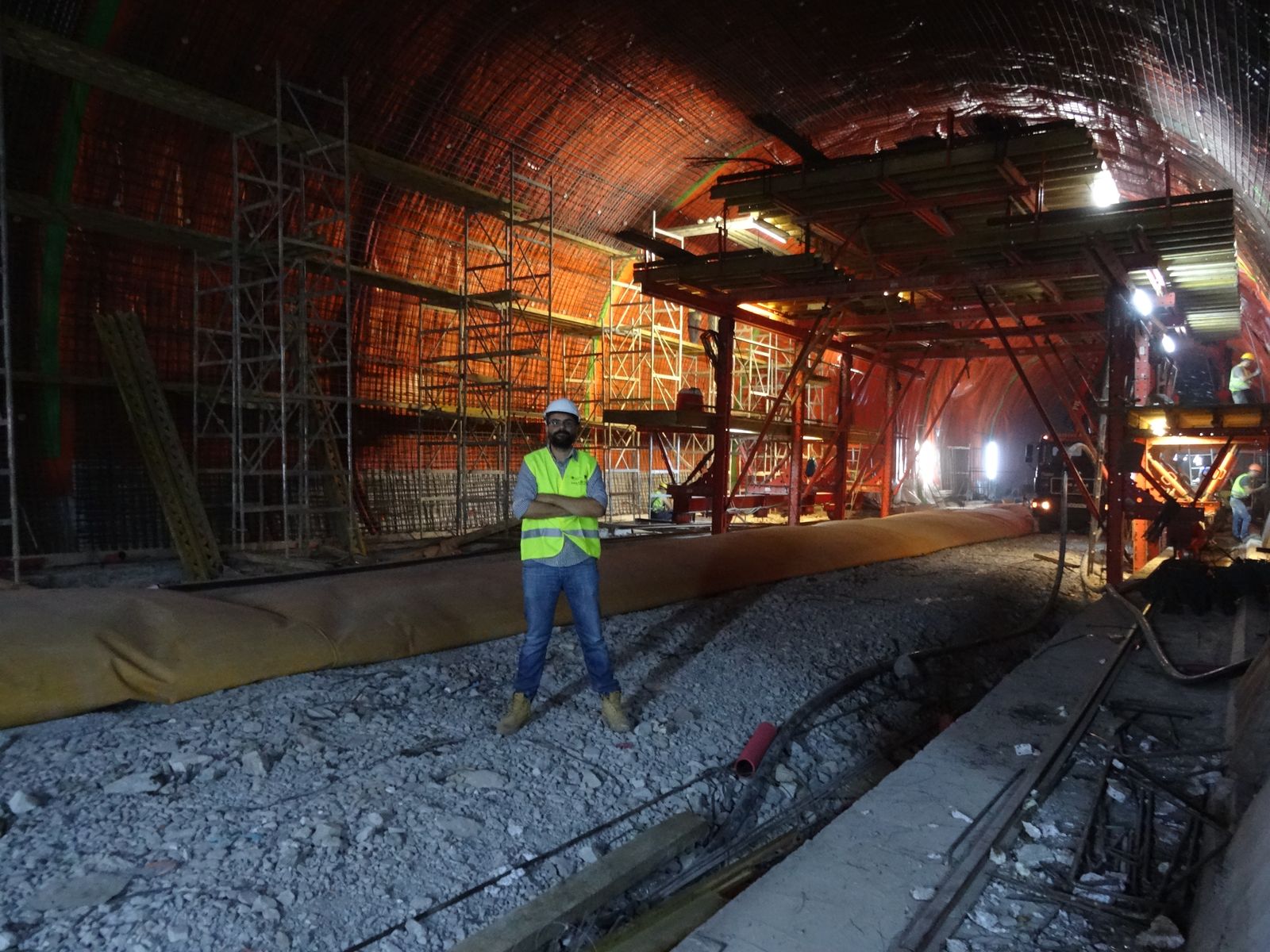
Klokova tunnel project consists of a twin tunnel with an approximate length of 2,900m (RHT 2,913m and LHT 2,894m). The two horseshoe shaped tunnels are of an internal radius of 5.5m and a maximum width of 11.0m accommodating 2 traffic lanes of 3.75 and 3.5m, respectively. The maximum overburden height reaches 535m, approximately. Klokova tunnel is the longest one out of the four IONIA Odos tunnels (the other three tunnels are the Makinia, Ampelia and Kalidona ones).

Fig 6
Fig. 9: Klokova tunnel (Left branch)
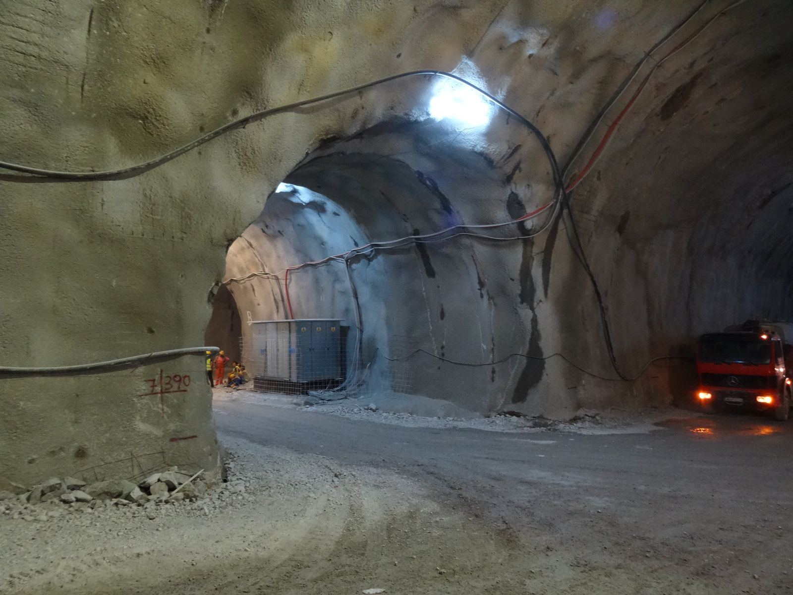
Fig. 10: Klokova tunnel (Cross-passage area)
Fig. 11: Klokova tunnel (Cross-passage area)

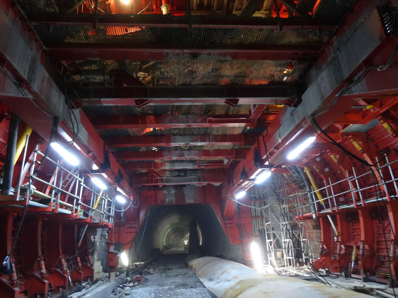
Each tunnel section is being excavated in two stages. The upper semi-section is excavated first and then the excavation of the lower section follows. At the areas where poor quality rockmass is encountered the solution of invert at the bottom of the tunnel is implemented.

The excavation progresses with the use of explosives and hard ripping techniques are adopted at the areas where poor quality rockmass is encountered. Primary support follows the principles of the NATM.

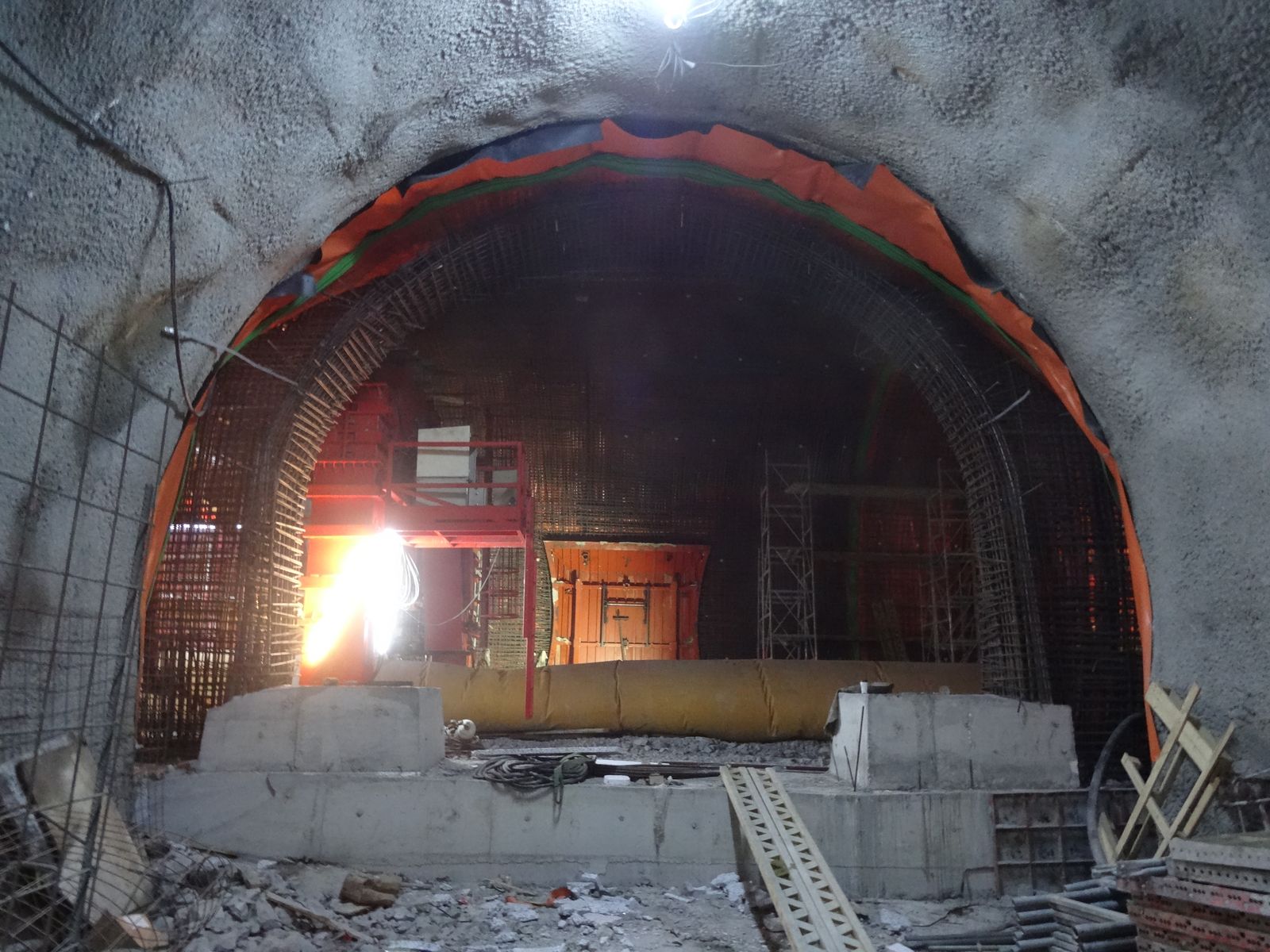
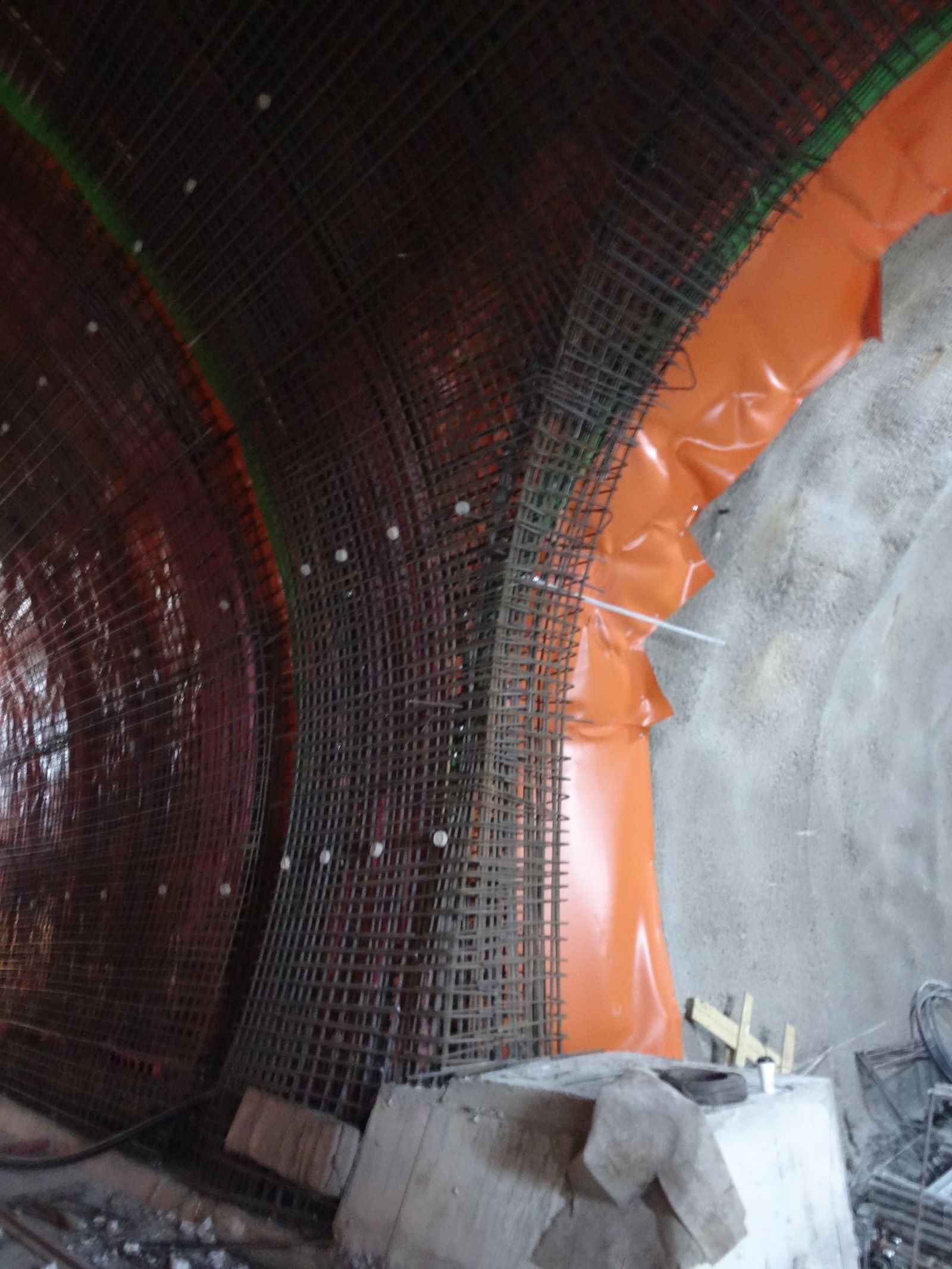
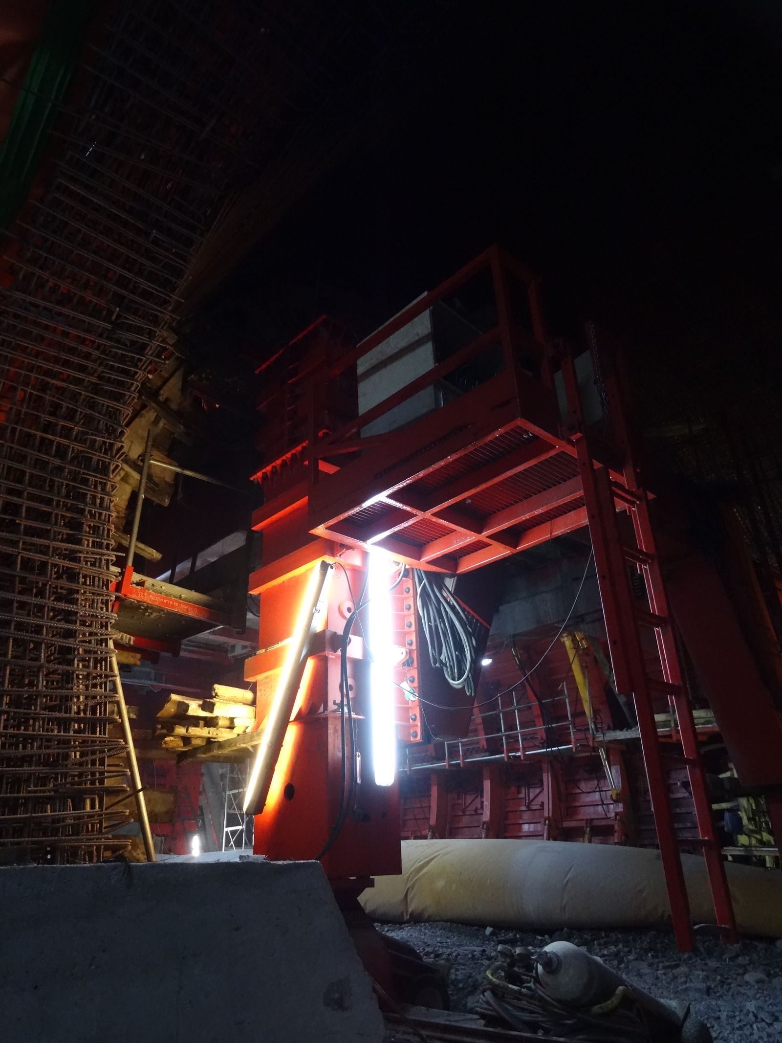
Fig. 12, 13, 14, 15: Klokova tunnel (Final lining works)

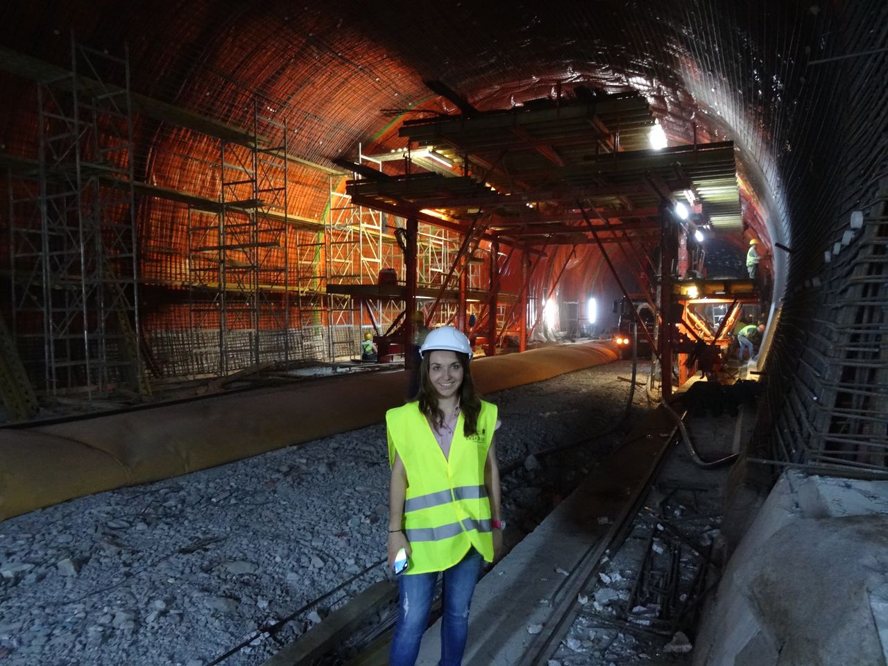
Geosysta personnel are feeling proud of having participated in the majority of the design’s geotechnical aspects of this major infrastructure project.

Fig 11

Fig. 16, 17: Geosysta personnel on site (Georgia Papavgeri & Thanasis Leventakis)

Being on site during these very moments when our design comes into “life” is priceless to us.

geotechSYSTAThe Geosysta Team

NATM is it New, Austrian or a Method?

NATM or New Austrian Tunneling Method has been for long time under scrutiny. Many disagree that was “NEW” in 1957 (Kovari 2003, Jaeger 1979) when it was introduced by L. von Rabcewicz. Many more have disagreed with the term “METHOD” such as Kovari 1993.

The term “NEW” was introduced by Rabcewicz to distinguish what he was proposing in relation to the current at that time “old” way tunnels were built, which was mostly with steel and wood lagging or/and brick arching.

For example in figure 1 the support method “mining and timbering method” is shown. This method was used for New York tunnel extension of the Pennsylvania railroad named the East River Tunnel. This tunnel was constructed between 1904 and 1909. As can be seen heavy timbering was utilized to support the crown which is excavated sequentially but due to the heavy and condensed timbering, space is limited.

Fig.1: New York tunnel extension of the Pennsylvania railroad (Gutenberg EBook )

For the same project in locations of soft rock or in general soft ground the following support method was used as described: “Where the rock was penetrated and soft ground showed in the roof, poling boards were driven ahead over the crown-bars”.

Fig.2: New York tunnel extension of the Pennsylvania railroad (Gutenberg EBook )

The Wislon Tunnel, Honolulu was excavated around 1954 and the “American support method” was used in which “two vertical slots, one each side of the tunnel, into which the next set of vertical posts could be placed.” Excavation advance step was around 1.2-1.5m. Due to the nature of the material a “progressive sloughing or spalling caused the upper part of the face to assume a more nearly veridical slope” also in some areas dome shaped over break was formed which was packed with timber as can be seen in figure 3 (Peck, 1981).

Fig. 3: Wislon Tunnel, Honolulu (Peck 1981)

In the next figure the successive steps of the “old” Austrian tunneling or “old” tunneling method can be seen. The support of the tunnel is made initially by densely packed timbering and then a final lining composed of a thick brick wall is constructed.
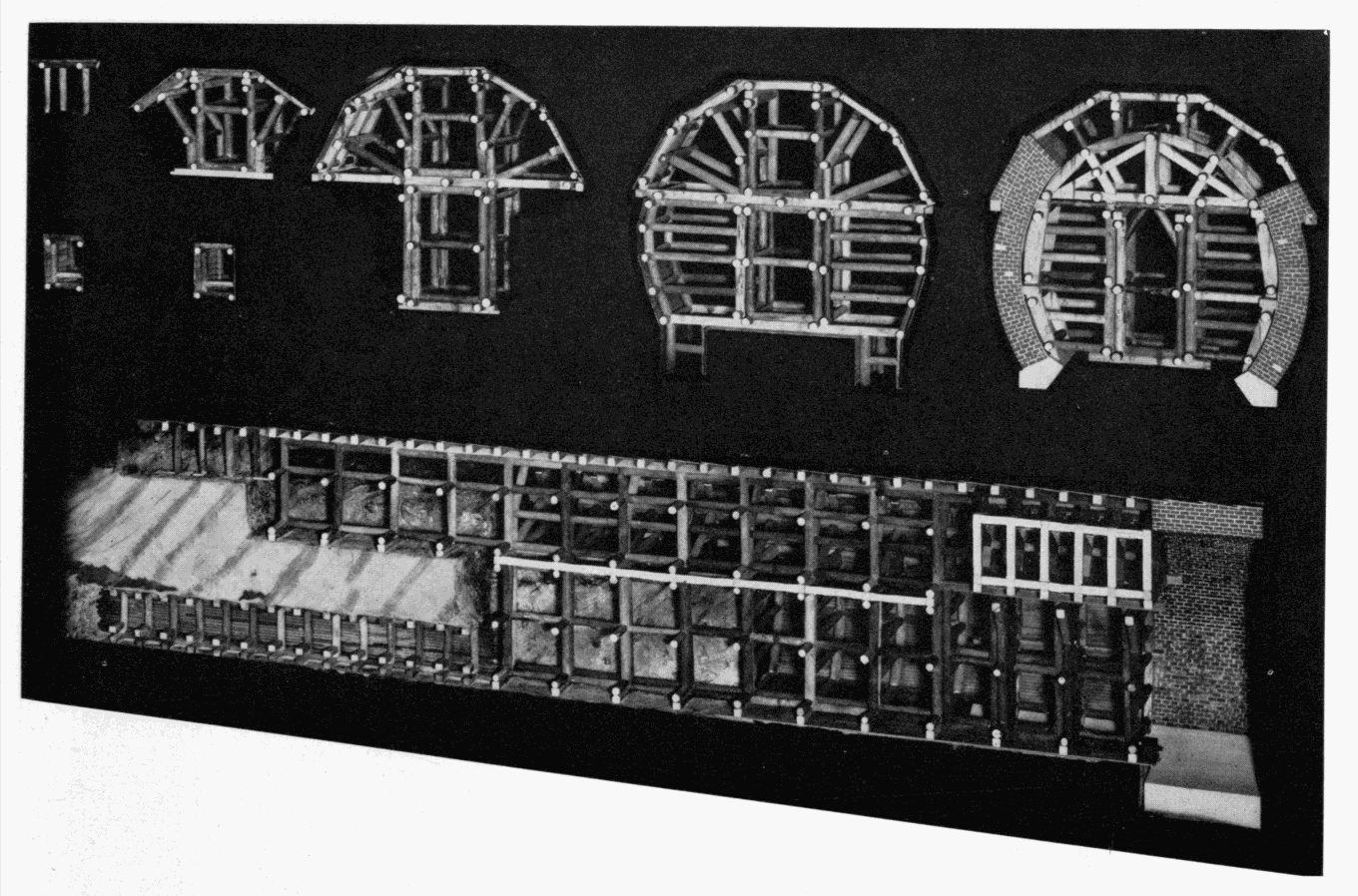
Fig. 4: The successive states in the enlargement of a mid-19th century railroad tunnel, using the Austrian system of timbering (Smithsonian Institution United States National Museum Bulletin 240).

The term “NEW” was used to distinguish from the “old” or traditional way of excavating and supporting tunnels. Kovari, 2003 provides a thorough literature review regarding the use of rock bolts, shotcrete, steel ribs and the combination of these methods. In his paper provides historical literature regarding the use of all these support methods way before Rebcewicz proposed the “NEW” way of tunneling. For example he mentions about a rock bolt procedure published in 1919 with a subtitle “Mine drift support with iron anchors”. Also in his opinion a major advance in rock bolting and shotcrete was made at the 42km Delaware Water Supply Aqueduct in New York in which “…instead of the usual steel ribs (Nolan, 1952). On November 8, 1950 permission was given to the contractor with several conditions. Among them were the application of steel roof ties (channels bolted to the rock) and gunite the rock as soon as possible after bolts and plates are put in place” (Kovari, 2003).
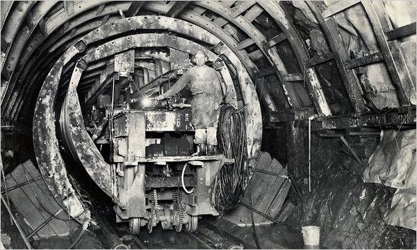
Fig 6. Working on the Rondout-West Branch Tunnel of the Delaware Aqueduct in 1942. Cracks have caused flooding in Wawarsing, N.Y., in Ulster County.

Prof. Jaeger states that the analysis in which the rock and support interact provided by Maillart (1922, 1923) and Andrea (1926, 1961) “…is more realistic than Rabcewicz’s approach [and] could have led to an early discovery of the NATM. It did not.”

Rabcewicz promoted a “NEW” way of tunnel support in which “using shotcrete and rockbolts (Austrian patent 1956) [could] cut time and problems considerably” (Jaeger, 1979). So was this actually a “NEW” method at that time? Does it really matter? Was Facebook the first social media network? No, but probably due to better marketing or better programming or some other details, became the first choice. Probably it was the same way with NATM, better marketing? Better detailed approach? Better specifications? Nobody exactly knows, but one thing is for sure, today when rock support with shotcrete – rockbolts and steel sets is proposed, immediately NATM comes to mind.

Criticism continues in relation to the term “METHOD” and especially that the surrounding rock becomes a load bearing element. In 1980 the Austrian National Committee on Underground Construction published the following statement:

“The New Austrian Tunnelling Method (NATM) is based on a concept whereby the ground (rock or soil) surrounding an underground opening becomes a load bearing structural component through activation of a ring – like body of supporting ground”.

The critic of such a statement describing a method of utilizing the ground as rock bearing element is not unique to NATM but it is the norm for all tunnel support systems even the “old” ones.

It is very interesting to note that the idea that the ground is the major load bearing element was understood as early as 1922 by Maillart from the experience gained from the Simplon tunnel with well over 2000m of overburden constructed in the Alps.

It is possible that the statement: “ground surrounding an underground opening becomes a load bearing structural component..” was another marketing trick. People working underground need to feel safe! The “stronger” the support the safer the miners feel. But what is a “strong” support? It is easily understood that a densely packed timber support shown in Figure 1, 3, 4 and 5 can provide a much better sociological effect than 10 rock bolts and a thin 20cm shell of shotcrete (fig 7).
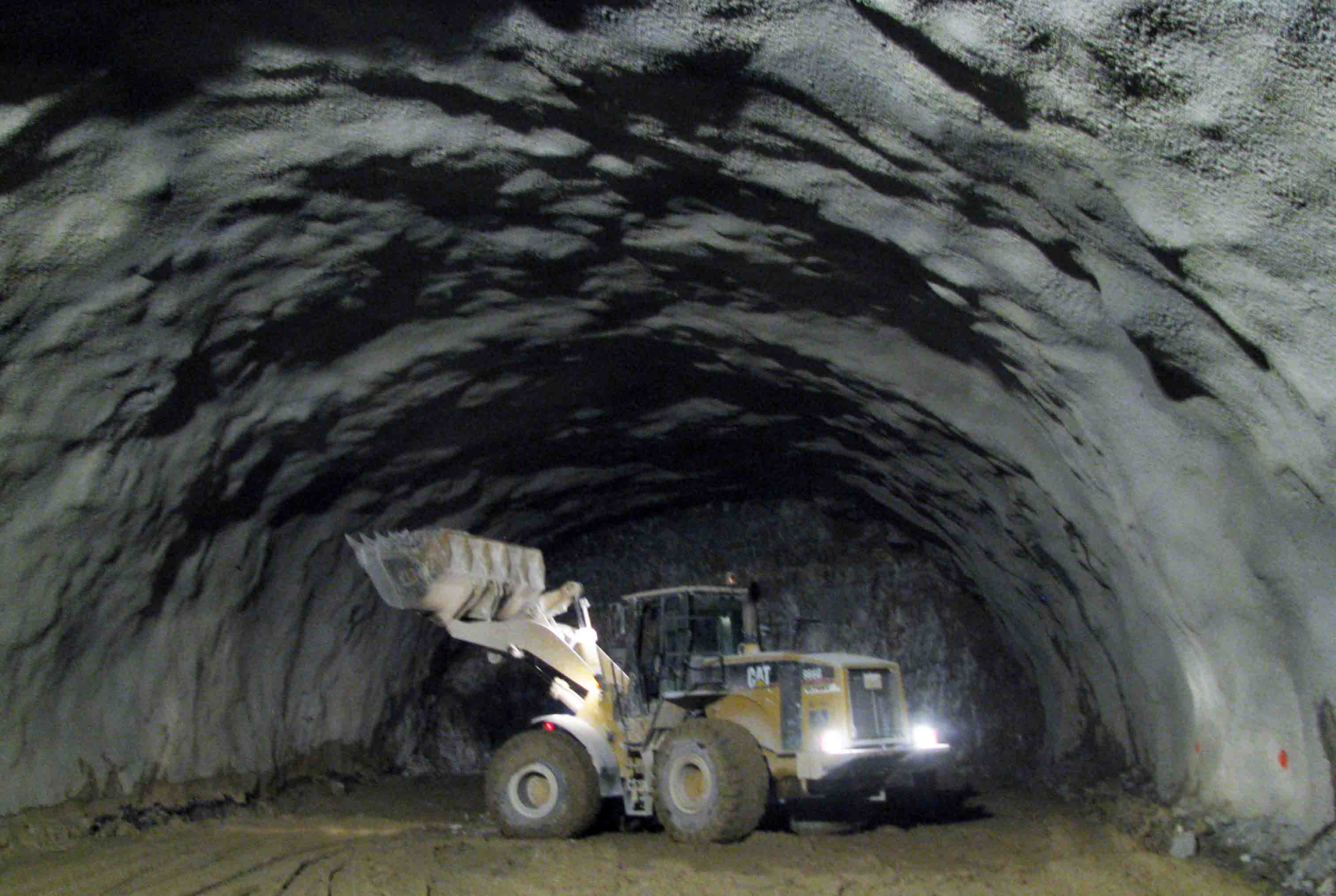
Fig. 7: Shotcrete and bolts for tunnel excavation with NATM

Even today the psychological effect is very important. Many times mines may chose thick steel ribs (HEB200) every 1.0m spacing considering that it is safer than let’s say 20cm of shotcrete with lattice girders.

It is possible that the “load bearing ground ring” which is utilized in one way or another in any underground opening was baptized as the “METHOD” in NATM in order to make miners “feel” safer with this “light” support. Any other explanation could be possible but the fact is that every underground opening has to utilize the ground as a load bearing element and not only if NATM is used.

It can be said that NATM was neither “NEW” neither of “AUSTRIAN” origin or a “METHOD” but at the same time a great respect is deserved to the Austrian Engineers and Miners that promoted this type of support that has since utilized all over the world.

Comments are welcomed.

Here is an interesting forum on the topic. Visit Underground Geomechanics Group in LinkedIn for interesting discussions.

References:

  1. Brace J. H., Mason F.  and Woodarm S. H., (1910). “The New York tunnel extension of the Pennsylvania railroad. The East River Tunnels”, The Project Gutenberg EBook of Transactions of the American Society of Civil Engineers, vol. LXVIII
  2. Hewett B. H. M. and Brown W. L. (1910). “The New York tunnel extension of the Pennsylvania railroad. The East River Tunnels, Paper No. 1159”. The Project Gutenberg EBook of Transactions of the American Society of Civil Engineers, vol. LXVIII
  3. Jaeger C., (1979). “Rock mechanics and engineering”, Second Edition, Cambridge University Press.
  4. Kovari K., (1993). “Erroneous Concepts behind NATM”, Lecture given at the Rabcewicz-Geomechanical Colloquium in Salzburg, Octobre 14, 1993.
  5. Kovari K., (2003). “History of the sprayed concrete lining method – part II: milestones  up to the 1960s”, Tunnelling and Underground Space Technology 18.
  6. Peck R. (1981). Soft ground tunneling, Balkema

Fiber reinforced shotcrete or wire mesh for tunnel support

When tunnels are excavated with conventional drill and blast operations or via mechanical excavation for softer material, the quickest way to support is the use of shotcrete. This method is called Sprayed Concrete Lining (SCL) in the UK and in other countries it is named as New Austrian Tunneling Method (NATM). In reality NATM is more than just the sprayed concrete lining and erroneously every tunnel support utilizing shotcete is named NATM but another post will cover this issue.

In this post I would like to make some points regarding the use of fibers or wire mesh in the reinforcement of shotcrete used for tunnel support. A great amount of literature exist regarding this issue and even more laboratory tests verifying that it is better to use fibers to reinforce shotcrete. This is because the shotcrete becomes more ductile when fibers are used in relation to just plain shotcrete and ductility is good in tunnel support.

The issue is what happens in larger displacements? When the shotcrete will crack? Would we want shotcrete to crack? How much cracking is acceptable? And if cracks occur does fibers or wire mesh do a better job?

When you excavate a tunnel you would like to have a ductile support that can accommodate some displacements. In this way you stabilize your tunnel using the ground as a supporting element and at the same time you gain in cost by using a lighter tunnel support. This is clearly demonstrated with the convergence – confinement diagrams (fig 1).

Convergence – confinement diagrams for tunnel support

In the stiffer support the yield point (failure of support) is where the stress – displacement becomes horizontal, in the less stiffer and more ductile the yield point is not clearly defined  but you could argue that at some point the displacements become too large with little offered additional support.

The equilibrium point is when the support stress – displacement curve meets the rock stress – displacement curve. If the support has not reached the yielding point, then you have “supported” your tunnel. If the yield point (for simplicity, the horizontal portion of the line) is beyond the rock curve then your support has failed to support the tunnel.

Back in our issue, what type of reinforcement to use? Steel fibers or wire mesh for tunnel support?

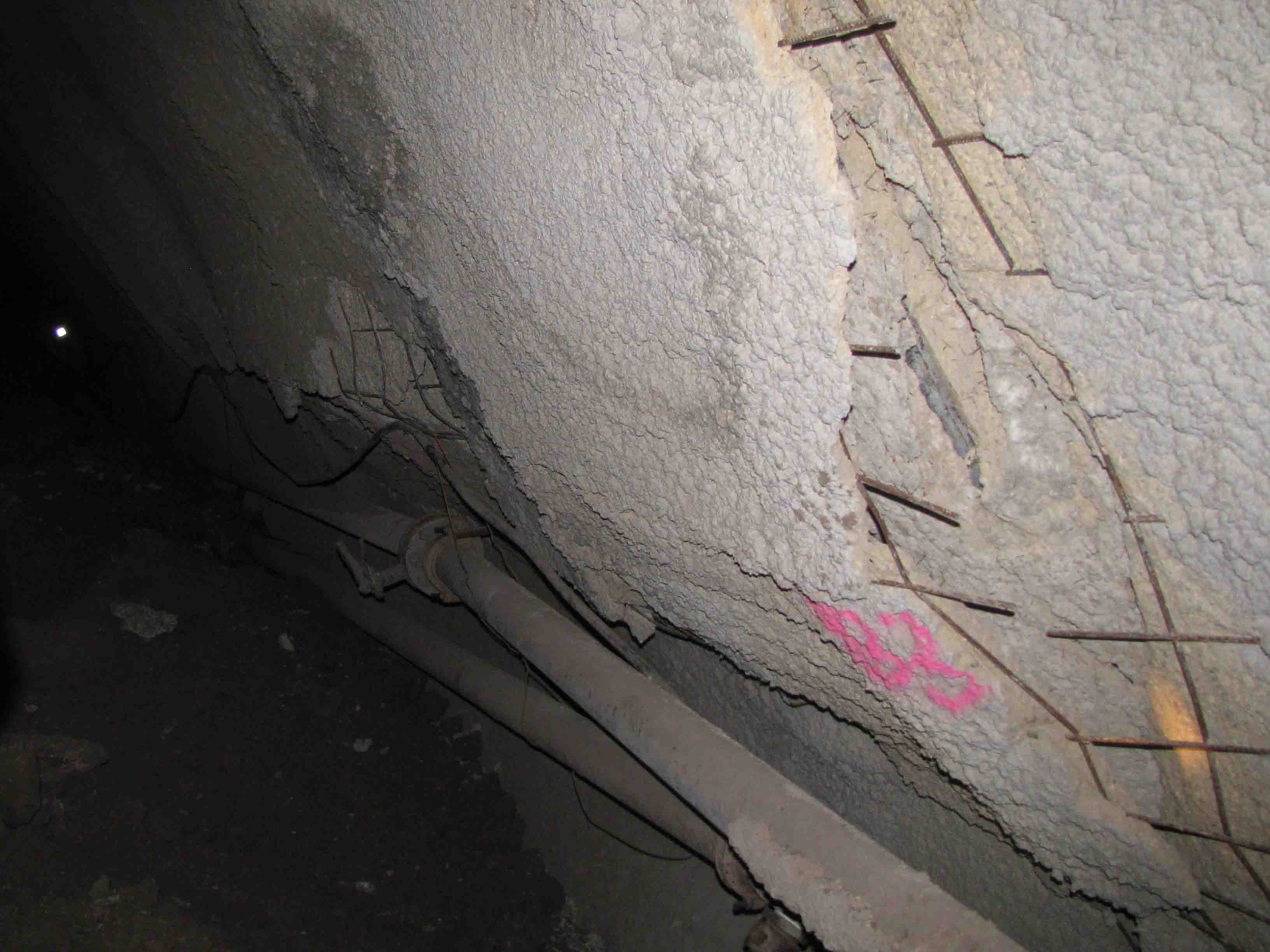
In the following photograph an area in the tunnel can be seen where too much displacement has taken place. The shotcrete has been severely cracked but is still standing and some support is offered due to the presence of the wire mesh (and bolts).

Shotcrete with wire mesh  for tunnel support

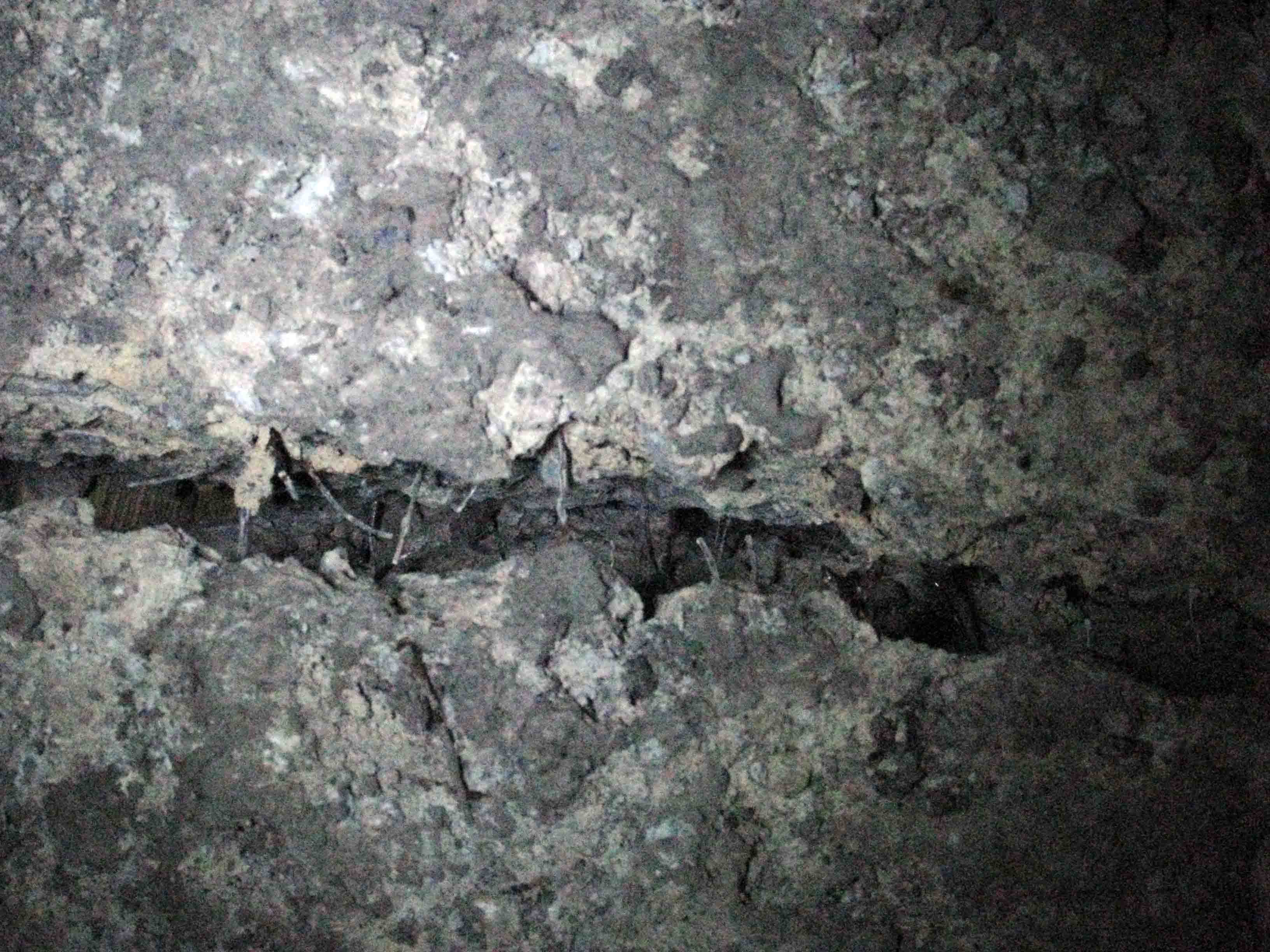
If the shotcrete was reinforced with fibers and such displacement had taken place, large chunks of shotcrete would had detached and fallen. This could harm personnel and equipment. This can be seen in the next photo where a crack has formed in fiber reinforced shotcrete and a gap where the fibers have been detached from the shotcrete.

steel fiber reinforced shotcrete for tunnel support

During construction, the use of fibers is more easily executed because the labor to erect the mesh is more time consuming. Also the mesh may not be able to follow the profile if inappropriate blasting has been executed in hard rock. On the other hand steel fibers are abrasive and can produce maintenance problems to the shotcrete equipment, are more dangerous for injuries during spraying and can more easily be “reduced” by the contractor without anybody knowing.

So coming back to the question of what type to use in tunnel support, one could argue that when you anticipate large displacements you should use steel wire mesh (maybe in collaboration with fibers) and when you anticipate small displacements steel fibers are appropriate and adequate.

In any case the primary support selection for tunnel construction requires careful and meticulous planning. The use of wire mesh can at least protect workers of uncontrolled collapse of shotcrete chunks in severely displacing rock masses.

Please comment for a fruitful technical discussion…

Post update 06/06/2013:

David Oliveira has posted in his popular and highly scientific LinkedIn group  Underground Geomechanics some very interesting comments and has promoted significantly the discussion. Please visit and contribute if you like. Thanks David!