Category Archives: Geotechnical information

ISSMGE Paris 2013. What did you miss?

A brief feedback from Chrys Steiakakis

A brief summary  for all the people that could not make it to the 18th International conference on soil mechanics and geotechnical engineering held on Paris between Monday 2 and Friday 6th of September 2013. The conference main theme was “Challenges and Innovations in Geotechnics”.

The conference commenced with the former president J. L. Briaud presentation of “The State of the Society” in which a very interesting point was his 10 rules for success.

J. L. Briaud presentation of “The State of the Society”

The conference continued with the 8th Terzaghi Oration invited lecture from Susan Lacasse of the Norwegian Geotechnical Institute (NGI).

Susan Lacasse presentation “Protecting society from landslides – the role of the geotechnical engineer”

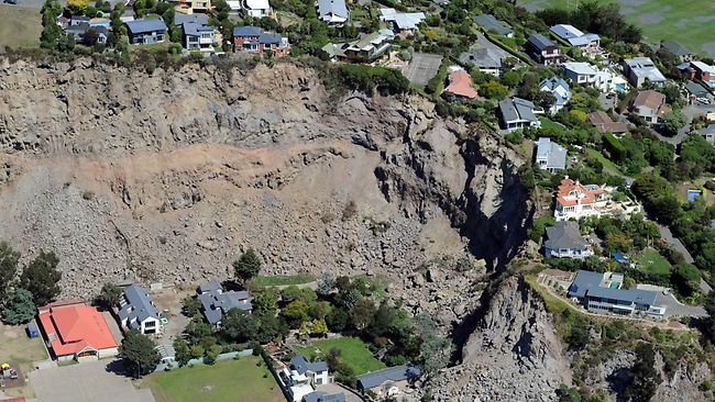
The title of the lecture was “Protecting society from landslides – the role of the geotechnical engineer”. The lecture presented case studies of landslides, their causes and the way they were analyzed and treated. Very interesting was the Kattmarka landslide that occurred on March the 13 2009 (which incidentally was Friday the 13!) and was caused because of the road construction. Main issues that led to the landslide were among others the limited geotechnical investigation and geotechnical design.

The first day continued with the Ishihara lecture presented by George Gazetas from the National Technical University of Athens (NTUA). The presentation title was “Soil-Foundation-Structure systems beyond conventional seismic failure thresholds”.

George Gazetas presentation “Soil-Foundation-Structure systems beyond conventional seismic failure thresholds”

He presented a novel approach of designing shallow foundations that are not designed to behave elastic in earthquake loading but to be able to work in extreme conditions and allow for uplift and bearing capacity slippage with acceptable limits of temporary and permanent deformations (settlements). This approach is contrary to current codes but it was shown that it could avoid structural damage and collapse.

The conference continued with the Manard Lecture presented by J. L. Briaud with title “The pressuremeter test: Expanding its use” in which he explained how to correctly utilize the PMT, how to execute the drillings and what the advantages of the pressuremeter test are. Furthermore he gave some reference values for preliminary design and some further extend of the test in liquefaction.

J. L. Briaud presentation “The pressuremeter test: Expanding its use”

A.Sim of Soletanche-Bachy provided an excellent presentation regarding the construction challenges and difficulties for the new Bugis Station and associated tunnels for the Mass Rapid Transit in Singapore.  Especially interesting were the methods used to overcome the passage of the tunnels and the station under or very near buildings.

A.Sim of Soletanche-Bachy presentation

Professor R. Jardine of Imperial Collage presented the Bishop Lecture in which he presented a state of art of laboratory testing and the use in research and practice. The lecture covered driven piles in sand and the detailed laboratory evaluation of these sands in order to predict pile behavior in static and cyclic loading.

Professor R. Jardine presentation Bishop lecture

The conference continued the next day with very interesting invited lectures that will be presented in a following entry.

How much does a geotechnical design cost?

I am sure that many geotechnical designers have either been asked this question or have had to answer it internally in order to price a project. After the offer has been prepared, comes the negotiation phase, where the owner of the project starts asking questions about the “high” price (in his opinion) or about a different offer he has had which was half that price!
I would like to point out some aspects that come into play in this negotiating tango between the Consultant and the Owner and some pitfalls that can come about with relation to this issue.
In geotechnical engineering a design is never “easy” or “simple” and this is because the ground is inherently variable, anisotropic and with minor details that cannot be easily assessed but nevertheless can have a detrimental effect during construction. Do we forget this, many times in our practice?
Pizza
So how do you go about performing a geotechnical design? A geotechnical investigation is executed initially with a predefined number of boreholes, usually less than we would like and a selective number of field and laboratory tests are executed. This investigation may be based on prior experience of the area but often it is not. The depth and location are governed with minimum information and mostly based on the structure to be constructed. Then with the geotechnical information gathered and evaluated the subsurface is formulated and the geotechnical design is executed, based on some form of standard (Eurocode, LRFD etc).
So the question now becomes “how many man hours will your engineers work determining the price you will ask for?” So in an effort to reduce the cost of design, the limited geotechnical investigation parameters are used with some partial factors of safety and the calculations are executed with nice software for bearing capacity or slope stability etc and the design is completed, on time, satisfying the standards and everybody is comfortable over the outcome. So how many man hours does such a procedure require? Don’t you think you should reduce your offer?
This is a recipe for disaster. In order to cut the cost of design, many things that should have been evaluated are not, inexperienced engineers work in the office with the software that they know so well but at the same time they may completely lose touch with the actual conditions or the geotechnical details that will actually control the performance of the project.
The cost of performing a geotechnical design is not merely the man hours spent doing some mainstream calculations but the time and experience that has been devoted to evaluate the most probable conditions and the most unfavorable conceivable deviations from these conditions and how they will affect the proposed project. This is not an easy task; it needs great experience (shouldn’t this be paid?) and many hours of thinking, sketching, performing simple hand or computer calculations, revisiting the site and the site investigation information etc. But this cannot be easily measured or quantified and produced as a cost estimate. So how can two Consultants compete when one routinely executes such practices and the other doesn’t? Sometimes luck favors the bold so the second consultant could have the same track record as the first one. And if a failure or excessive deformation etc happens then it is easy to blame it on “the unforeseen geological conditions”. No harm done! Just the budget and time of the project may significantly increase, maybe increase orders of magnitude in relation to the reduction that was achieved with the negotiation of the geotechnical design fees or with the selection of the geotechnical consultant with the lowest bid.

Factor of safety and probability of failure, E. Hoek  - Practical Rock Slope Engineering
So Geotechnical Designers should advertise in more detail what they actually do, advertise the experience and expertise they pose in house and the way they tackle a geotechnical design. They may need to make the owner aware of what is at stake with an improper geotechnical design even if it meets all available standards.

Owners should take a step back and think; is the lower bid the best way to go? Is the reduced price that was achieved after hours of negotiations worth the risk of an improper geotechnical design? What is the gain of a reduced cost of design in relation to the actual cost of construction? Never forget that you get what you pay for and this in geotechnical design can really have a significant cost!

Shanghai building foundation failure, http://activerain.com/blogsview/1524118/nashville-building-inspection-foundation-failure-what-is-wrong-with-this-picture-3-2-10

Slope failures, landslides and mines

On 11 of April 2013, around 9:30 p.m. a large slide (maybe the largest) in the northeast section of the Kennecott mine occured (fig 1). The slide was preceded by slope movements that reached ~50mm per day. Two major questions could be raised, why this slide occurred and could it have been predicted before hand and remediated?

Kennecott mine

These are very difficult questions and require significant knowledge of the geology, geotechnical conditions of the area, operational practices, climatic conditions etc. In the following paragraphs some initial ideas regarding the stability of high mine slopes and some interesting references will be provided for interested individuals. The incident in Kennecott is an important lesson of how important continuous monitoring of slopes is in such mine operations.

I would like to start with a very interesting graph published by Hoek et al (2000), “Large-scale slope Design – A Review of the State of the Art”.

This chart presents slope height versus overall angle with solid markers representing unstable slopes and open markers represent stable slopes. This chart is for copper porphyry open pits. In this graph the Kennocott mine (Bingham Canyon) is also shown but not the April 2013 one.

It is very interesting to note that most of the unstable markers are located in a range between 35 and 45 degrees of slope angle. Although much information is required for detail evaluation of each point and why instability occurred, a trend can be seen. Can we assume that slopes designed bellow 32-35o would not provide stability problems?

In the next figure I would like to focus on scale effects when dealing with mine slopes in rock or even hard rock materials. In the down left side of the figure 2 a slope with 30 meters height is depicted. In the upper left one of 90m with the same spacing of joints and finaly on the right a slope of 500m again with the same spacing and trance length of discontinuities (figures adopted from Sjoberg, 1996).

What can be seen from this slope scale is that even solid lightly fractured hard rock can be seen as an accumulation of infinite rock items such as a gravel slope or sand slope, just with better interlocking. One additional question can be, “what is the effect of bridging (intact rock between discontinuities) in such large scale slopes”? Very difficult question but maybe the previous graph provides an explanation (maybe negligible?).

Is the scale effect, in relation to joint spacing, orientation and stress field producing a ductile (sand or gravel like) behavior that may control the overall stability?

In the left graph (Ross, 1949) tests on intact marble with different confining pressures are presented. On the right (Holtz, 1981) normalized stress – strain with different confining pressures for dense Sacramento sand are presented. As can be seen, both materials in low confining pressures present a brittle behavior and as confining pressure increases, the behavior becomes more ductile and strain hardening.

Strong rock and dense sand can have the same behavior in different stress scale? And if this is the case, should high slopes be treated in a different way? Neglecting cohesion and using a possible “critical state friction angle” approach in slope stability? This issue requires additional research and detailed case studies but at least we can have some perspective regarding to scale effects.

References:

Sjoberg J., (1996). Large scale slope stability in open pit mining – a review. Technical Report 1996:10T, Lulea University of Technology

Hoek E., Rippere K. H. and Stacey P.F. (2000). Chapter 1, Slope stability in surface mining, Hustrulid, McCarter, VanZyl (eds), Society for Mining, Metallurgy and Exploration

Ros Μ. und Eichinger Α. (1949). Die Bruchgefahr fester Korper (Eidgenoss. Material prufungs versuchsanstalt, Ind., Bauw. Gewerbe. ZUrich, l72), 246 pp.

Holtz R. D., Kovacs W. D., (1981). “An Introduction to Geotechnical Engineering”, Prentice Hall.

IAEG XII Congress: Engineering Geology

IAEG XII congressIAEG (International  Association for Engineering Geology) organizes the XII Congress that will be held in Torino (Italy) from 15 to 19 September, 2014. The topic of the IAEG XII Congress is: “Engineering Geology for Society and Territory” and aims to explore and analyze the role of Engineering Geology.


There are four main themes offered to participants:

  1. Environment: River Basins, Reservoir Sedimentation and Water Resources
  2. Processes: Landslide Processes, Marine and Coastal Processes,
  3. Issues: Urban Geology and Landscapes Exploitation, Preservation of Cultural Heritage
  4. Approaches: Applied Geology for major Engineering Projects, Education Professional ethics and Public Recognition of Engineering Geology

Deadline for abstract submission is fast approaching : 15/04/2013, while the estimated Deadline for Full Paper submission is September 30, 2013.

Proper amount of geotechnical investigation

The situation is like this: A major problem occurs in a bridge abutment and significant differential settlement between abutment and road is observed. The Owner decides to investigate the situation and assigns the job to a joint collaboration between a University and a Geotechnical Consultancy Firm.

The collaboration requests the execution of three boreholes to a depth of 30m, execute a number of consolidation tests some in a private laboratory and some in the laboratory of the University, together with other appropriate soil tests such as gradation, shear strength etc.

The collaboration provides a report in which it is stated that the previous geotechnical investigation did not evaluate properly the soil conditions because only one (1) drilling of 20m depth was executed in the abutment and did not evaluate properly the thickness of a compressible clay layer. Also based on the 15 consolidation tests executed by the collaboration, the coefficient of consolidation and the preconsolidation pressure estimated by the previous Geotechnical Consultant were optimistic. The previous consultant had executed three (3) consolidation tests.

So the conclusion of the report was that the problem was due to the optimistic evaluation of settlements made by the previous Geotechnical Consultant which had executed only one (1) drilling of twenty (20) meters and limited consolidation testing.

It is very easy to come to a “correct” solution after a significant amount of geotechnical investigation (money spent) has been executed in an area where a problem has occurred. The problem is known, some geotechnical information is available and the investigation can be targeted appropriately.

But how easy is this to be done from the start of a project? Most people involved in geotechnical investigation know how difficult is to persuade the Owner, Contractor etc to execute even the minimum required investigation not to mention the increased difficulty to persuade for additional investigation in an area where a hint of geotechnical problem is speculated.

In the fast track way that most projects are executed these days how can the geotechnical investigation and design produce “accurate” results?

How can we persuade the Clients that less is not more in geotechnical investigation and design? Food for thought.

SPT field testing

Today I came across a very interesting paper regarding site investigation with SPT and CPT. In this paper written by J. D. Rogers, the historical development of SPT from its creation from Charles R. Gow, to its modification and standardization by K. Terzaghi and A. Casagrande and its standardized use today are presented.

The road to SPT corrections and the reasoning behind them is provided while a critical evaluation of these corrections is presented. Some pitfalls in the execution and evaluation of the results can be found in this paper. Practitioners will find it to be a good review regarding SPT and new geotechnical engineers can understand the limitations of the methods.

Some issues that are not covered in detail regarding SPT testing and in my opinion are very important are the operator’s (driller) proficiency and the appropriate supervise. This is of paramount importance and I would like to share some insight.

I was present at an SPT execution in a hot summer day around 2:00 pm, the test had started while the geologist in charge and I were evaluating some outcrop geology not too far from the drill. As we started approaching the drill (the driller could not see as yet) I observed a very lazy move in the way the rope was tightened in the rotating drum.

The SPT hammer (a safety donut type, picture 2) was not traveling the appropriate height before it was released for its free fall. Even when it was released the driller was somehow holding very loosely the rope so the energy of impact was even more reduced. As it is easily understood the SPT blow count would be significantly higher than that required for the specific conditions if the test was executed correctly.

Another time I observed a driller (probably wanted to impress his supervisor) executing the test in a very quick pace. During this quick pace he was lifting the donut hammer and not releasing it as quickly needed for that pace. The safety donut was hitting the rod in the upper end (picture 3), displacing it upwards from the ground. It is easily understood that SPT blow counts again would not be correct.

Automated SPT execution equipment are available that could eliminate these issues but they are not a standard practice due to cost and other operational issues. Even if such equipment were used, other problems could arise during SPT execution.

It is very important to understand that SPT values are numbers with high scatter, even for very homogeneous materials, when evaluating ground properties, great care and judgment must be executed. Corrections can be found and applied but human errors are not so easy to predict or account for.

Engineering Geology – Christchurch Earthquake Presentation

On February 2011 an earthquake of M=6.3 magnitude struck Christchurch in New Zealand causing the death of 185 people. This earthquake has particular significance for geotechnical engineers, since a number of geotechnical phenomena were manifested during and after the event. Liquefaction in a wide area and landslides (rockfalls), caused widespread damage across Christchurch especially in the central city and eastern suburbs.

The 22nd February 2011 Christchurch earthquake was an aftershock of the September 4th, 2010 magnitude M=7.1 earthquake that struck the western part of the city. As a consequence the buildings and infrastructures that were already weakened, were severely damaged during the Christchurch earthquake.

The Geological Society of London is hosting a presentation about Christchurch earthquake on Thursday 11 April 2013. The presentation will focus on the geological and geotechnical aspects of the earthquake and on future development of Christchurch city.

See here for more details about the event and the speakers.

christchurch-earthquake
Landslides caused by Christchurch earthquake
www.news.com.au

Visual observations and field experience versus mathematical formulations and office work

Geotechnical Engineers, Engineering Geologists and Geoprofessionals in general are involved in evaluating and quantifying earth processes, earth materials, and human intervention on or in the earth in a way that can be used to manage geological risk and to produce safe and economical structures such as tunnels, dams, cuts etc.

In order to produce such evaluation the geoprofessional needs to understand the geology of the area, to evaluate the material properties and to analyze the problem at hand based on sound engineering principals.

Unfortunately this does not happen all of the time, either because many are focused in desk studies and numerical models without proper understanding of the actual conditions and others because they oversimplify and base their estimates solely on visual observations of the area.

The problem is that in order to effectively manage and work with models one needs to spend increased amount of time in the office studying the method and learning how to implement in a computer (not much time left for field work!). On the other hand the field is time consuming and usually far away from the office… (not much time to spent in front of a computer!).

Can we combine these two? Many people and consulting offices do, but there are others that don’t.

I will present an example where the lack of field work and understanding scree coreof the situation can produce significant errors. In figure 1 the drilling core of cemented talus is presented. The material is classified as (GP) per ASTM 2487, SPT blow counts produce refusal of penetration and anyone evaluatingscree slope this material from the office would assign the following material properties c’=0kPa and φ’>37ο, and they would design a slope with maximum inclination of about 28o in order to have a FS of about FS>1.4. The reality is that this slope is standing vertical without any stability problems as can be observed in figure 2.

It is very important for geotechnical engineers to have a real understanding of field conditions.

How easy RQD estimations are?

RQD was introduced by D. U. Deere in 1964 for a quantitative description of rock mass. The RQD  is defined as the percent ratio of the sum of core pieces with higher than 10cm length to the total drill run.  Based on the percent or RQD from 0-100% the rock mass quality can be assessed. For example based on the proposal by Deere, rock mass with RQD<25% is characterized as “very poor”. If RQD is higher than 75% it is classified as “Good”.

The RQD estimation is generally easy in the field and has gained a wide popularity. There are issues that should be addressed every time such estimations are made in order to avoid misleading results. In the following some personal experience will be provided regarding this issue.

RQD should not be addressed blindly and only in relation to the length of the core sample for the following reasons:

  1. The diameter of drilling core used should be known and taken into account. In the ISRM Suggested Methods, Brown 1981 a NX (55mm) drill core is mentioned, but in recent years the diameter has significantly increased in many projects and the sample is no more 55mm but can easily be 110mm. The increased diameter has one advantage that better quality core samples can be obtained but at the same time they can include more discontinuities. It is not clear if you will obtain higher or lower RQD values without recognizing the joint system. In the first figure it is observed that the sample with smaller diameter presents more fractures (some may be due to drilling).RQD
  2. The type of drilling barrel is very important. Different quality of drilling can be succeeded with double barrel (which is suggested) or split double core barrel than single or triple core barrel. The triple core and the double split barrel usually produce similar results unless the material is very much fractured. In that case RQD values would be zero anyway.
  3. The driller’s capability may be among the most important aspects especially for rock masses that are fair and poor. In the same location, with the same equipment different drillers may produce different results. Sometimes the artificial fracturing due to drilling may be easily identified but many times they are not especially in certain types of rocks described bellow.
  4. The rock type is extremely important. Geological material wiSiltstone sandstone alteration in a folded structureth foliation and bedding can produce misleading results of natural discontinuities. Clayey like rock materials such as shale, mudstones, siltstones can produce false impressions of discontinuities that are made during drilling but appear to be natural.  In such materials especially when tectonically disturbed, they can appear as solid samples but have discontinuities that are not easily visible.  In such situation RQD estimates have to be used with great caution.
  5. Number of joint sets and orientation, especially orientation can have a profound effect on RQRQDD estimation. For example vertical or near vertical joints may produce 100% RQD in a rock mass that has a discontinuity spacing of just 11cm. This can happen even in horizontal joint sets and a have the following results of RQD=0 for horizontal joint with spacing of 9.9cm and 100% for joint spacing of 10cm!

So when evaluating RQD values,  due consideration should be given to the material type, Driller, drilling equipment, geology and structural features of the rock.