All posts by Chrys Steiakakis

About Chrys Steiakakis

Chrys Steiakakis is a practicing geotechnical engineer with more than fifteen years of experience in the field of geotechnical engineering. He earned his bachelor and master in mining engineering from the Technical University of Crete, Greece and a second master’s degree in Civil Engineering from Virginia Polytechnic Institute and State University, USA. He has been the technical director of engineering department of General Consulting ISTRIA for four years and now he is a partner and also provides his own consultancy services via Geosysta ltd. He has been involved in numerous highway, railway and mining projects. Chrys with his long term collaboration with the Technical University of Crete has participated in numerous research projects in the field of geotechnical engineering and rock mechanics and has provided self sustained seminars of geotechnical engineering in related areas for the Industry. His main field of experience covers all aspects of tunnel design, earthworks design and monitoring (slope stability, embankment in difficult ground, reinforced embankments and retaining walls), landslide investigation and mitigation, foundations for bridges and structures, risk assessment in geotechnical projects and value engineering in large projects.

Fiber reinforced shotcrete or wire mesh for tunnel support

When tunnels are excavated with conventional drill and blast operations or via mechanical excavation for softer material, the quickest way to support is the use of shotcrete. This method is called Sprayed Concrete Lining (SCL) in the UK and in other countries it is named as New Austrian Tunneling Method (NATM). In reality NATM is more than just the sprayed concrete lining and erroneously every tunnel support utilizing shotcete is named NATM but another post will cover this issue.

In this post I would like to make some points regarding the use of fibers or wire mesh in the reinforcement of shotcrete used for tunnel support. A great amount of literature exist regarding this issue and even more laboratory tests verifying that it is better to use fibers to reinforce shotcrete. This is because the shotcrete becomes more ductile when fibers are used in relation to just plain shotcrete and ductility is good in tunnel support.

The issue is what happens in larger displacements? When the shotcrete will crack? Would we want shotcrete to crack? How much cracking is acceptable? And if cracks occur does fibers or wire mesh do a better job?

When you excavate a tunnel you would like to have a ductile support that can accommodate some displacements. In this way you stabilize your tunnel using the ground as a supporting element and at the same time you gain in cost by using a lighter tunnel support. This is clearly demonstrated with the convergence – confinement diagrams (fig 1).

Convergence – confinement diagrams for tunnel support

In the stiffer support the yield point (failure of support) is where the stress – displacement becomes horizontal, in the less stiffer and more ductile the yield point is not clearly defined  but you could argue that at some point the displacements become too large with little offered additional support.

The equilibrium point is when the support stress – displacement curve meets the rock stress – displacement curve. If the support has not reached the yielding point, then you have “supported” your tunnel. If the yield point (for simplicity, the horizontal portion of the line) is beyond the rock curve then your support has failed to support the tunnel.

Back in our issue, what type of reinforcement to use? Steel fibers or wire mesh for tunnel support?

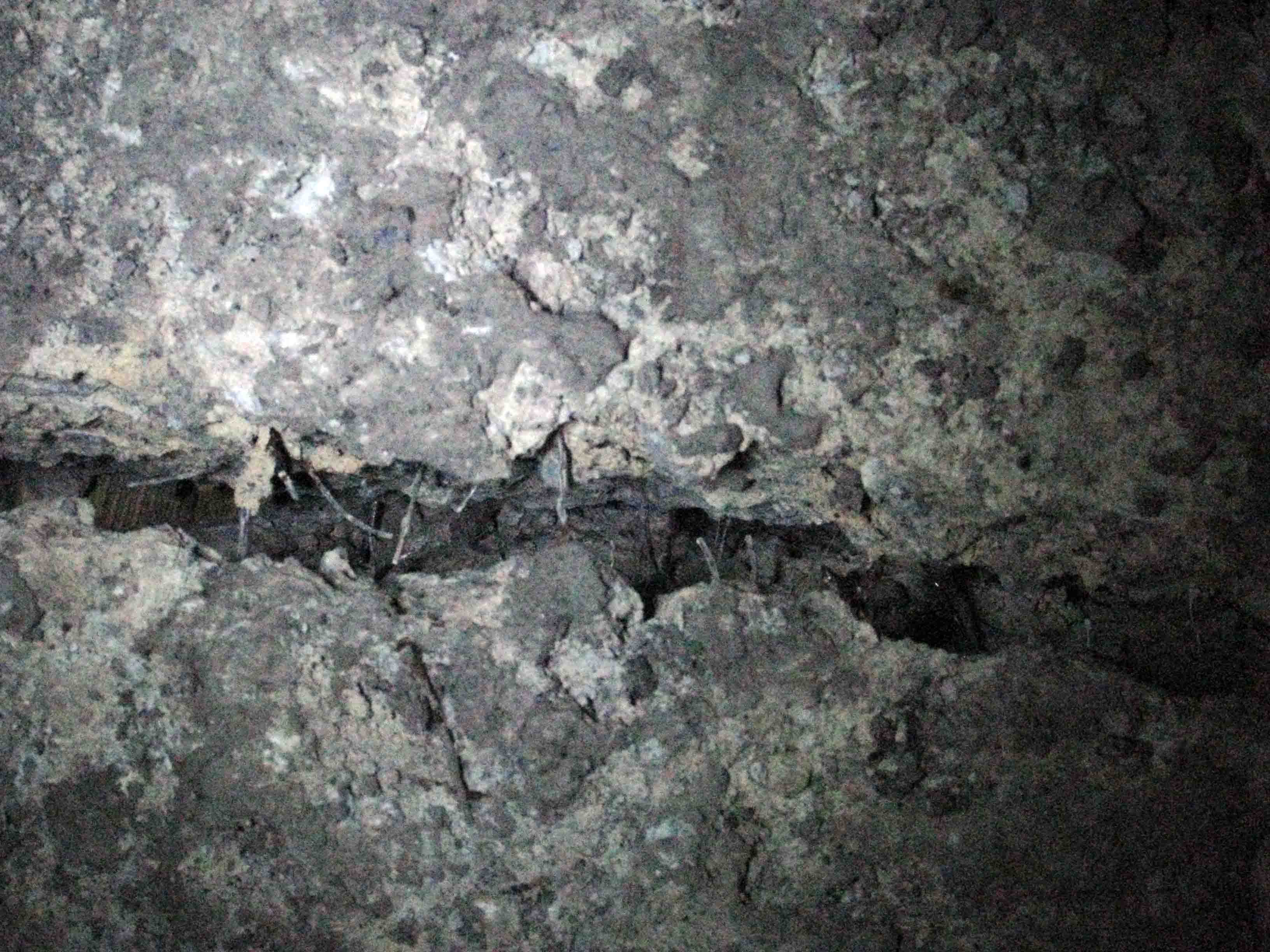
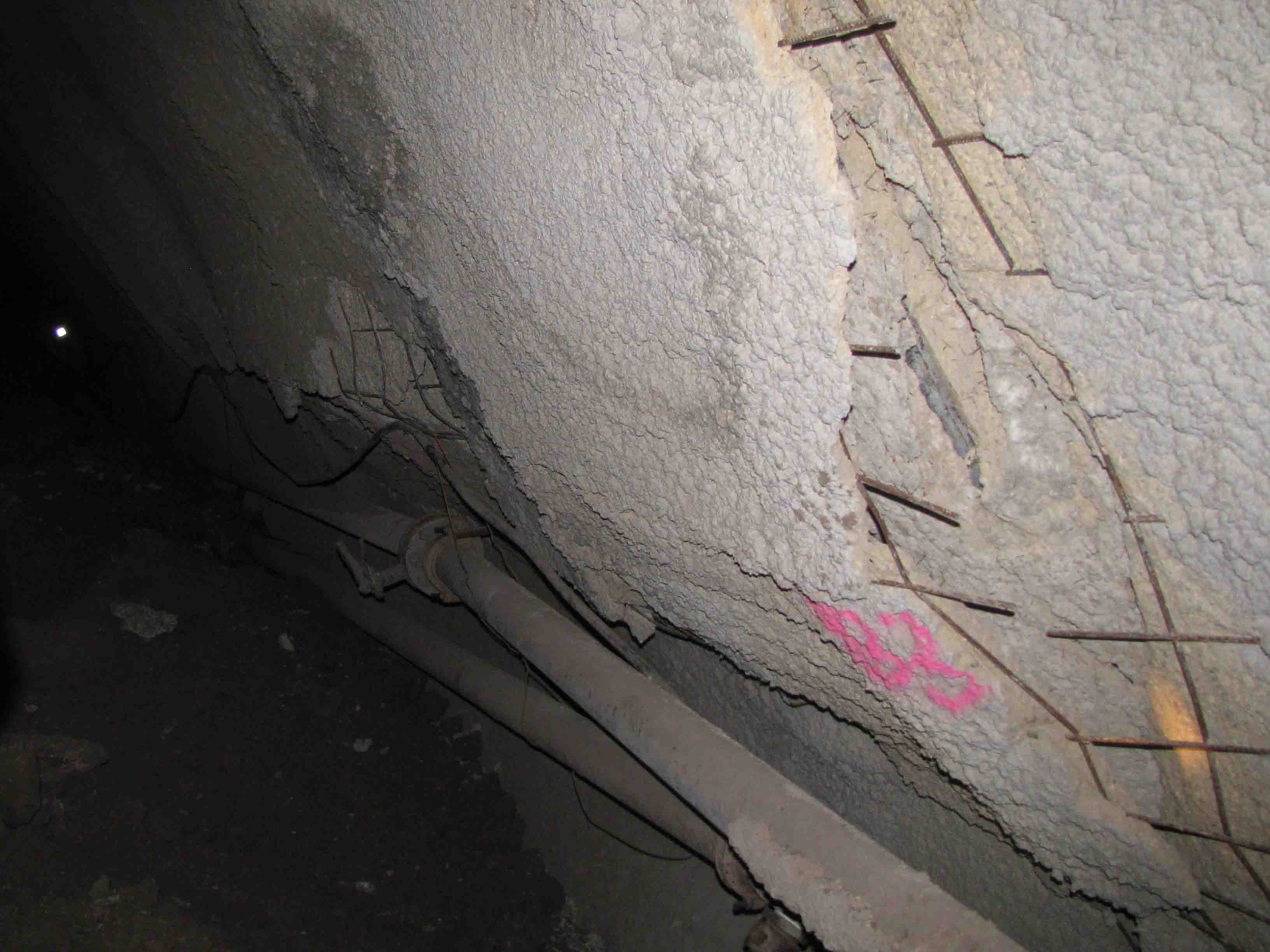
In the following photograph an area in the tunnel can be seen where too much displacement has taken place. The shotcrete has been severely cracked but is still standing and some support is offered due to the presence of the wire mesh (and bolts).

Shotcrete with wire mesh  for tunnel support

If the shotcrete was reinforced with fibers and such displacement had taken place, large chunks of shotcrete would had detached and fallen. This could harm personnel and equipment. This can be seen in the next photo where a crack has formed in fiber reinforced shotcrete and a gap where the fibers have been detached from the shotcrete.

steel fiber reinforced shotcrete for tunnel support

During construction, the use of fibers is more easily executed because the labor to erect the mesh is more time consuming. Also the mesh may not be able to follow the profile if inappropriate blasting has been executed in hard rock. On the other hand steel fibers are abrasive and can produce maintenance problems to the shotcrete equipment, are more dangerous for injuries during spraying and can more easily be “reduced” by the contractor without anybody knowing.

So coming back to the question of what type to use in tunnel support, one could argue that when you anticipate large displacements you should use steel wire mesh (maybe in collaboration with fibers) and when you anticipate small displacements steel fibers are appropriate and adequate.

In any case the primary support selection for tunnel construction requires careful and meticulous planning. The use of wire mesh can at least protect workers of uncontrolled collapse of shotcrete chunks in severely displacing rock masses.

Please comment for a fruitful technical discussion…

Post update 06/06/2013:

David Oliveira has posted in his popular and highly scientific LinkedIn group  Underground Geomechanics some very interesting comments and has promoted significantly the discussion. Please visit and contribute if you like. Thanks David!

Mohr – Coulomb failure criterion continued

Things to remember when using the Mohr – Coulomb failure criterion:

  • The linear failure envelope is just an approximation to simplify calculations
  • The failure envelope is stress dependent and will produce some kind of curvature if shear strength tests are executed in much different confining stresses (fig 1, from Duncan and Write, 2005).


  • According to Lade, 2010 the failure envelope is curved and at low effective stresses which can be found in superficial failures on slopes, the use of linear Mohr – Coulomb may be in the unsafe side. Soils without cementation do not provide any effective cohesion in very low effective stresses (fig 2, from Lade, 2010).


  • When the linear Mohr – Coulomb criterion is used it must be evaluated for the expected stress range in the field.
  • Small cohesion values will not produce significant errors when high effective stresses are anticipated in the calculation.
  • In low effective stress even minimum values of effective cohesion (in cohesionless soils) can produce significant errors in factor of Safety (FS) calculations.

References:

Duncan J. M.,  Wright S. G., (2005). “Soil Strength and Slope Stability”. Wiley, New York.

Lade P. V. (2010). “The mechanics of surficial failure in soil slopes”. Engineering Geology 114, pp 57-64.

The Mohr – Coulomb strength criterion

This is something that all geotechnical engineers should know but it is surprising how many do not! Just a brief overview of how the Mohr – Coulomb strength criterion came about.

The Mohr – Coulomb criterion is the outcome of inspiration of two great men, Otto Mohr born on 1835 and passed away on 1918 and Charles-Augustin de Coulomb born on 1736 and passed away on 1806.

The two men never coexisted but their brilliant minds contributed significantly in the scientific knowledge. The combination of two hypotheses gave us the Mohr – Coulomb failure surface.

Chronologically,  Coulomb was involved in military defense works (how much knowledge have we gained due to war!) trying to built higher walls for the French. In order to investigate why taller walls than usual were failing and try to built them to stand, he wanted to understand the lateral earth pressure against retaining walls and the shear strength of soils. He devised a shear strength test and observed (at that time, with his tests) that soil shear strength was composed of one parameter that was stress – independent named cohesion (c) and one that was stress – dependent, similar to friction of sliding solid bodies named angle of internal friction (φ). Probably he executed shear strength tests and found for different normal stresses (σ) different shear stresses (τ). By plotting these data on a (τ-σ) diagram he obtained the straight line denoted by the equation τ=c+σ.tan(φ) as can be seen in the next figure.

Coulomb failure surface

Mohr (1900) proposed a criterion for the failure of materials on a plane which has a unique function with the normal stress on that plane of failure. The equation for that was τ=f(σ) where τ is the shear strength and σ the normal stress on the plane.  With the use of the Mohr circles which is a two dimensional graphical representation of the state of stress at a point and the circumference of the circle is the locus of points that represent the state of stress on individual planes the Mohr failure envelope was proposed. The Mohr envelope was a line tangent to the maximum possible circles at different stresses and no circle could have part of it above that tangent curved line. (figure 2).

Mohr failure envelope

It is not known (Holtz et al, 1981) who first combined both theories but combining the Mohr failure criterion with the Coulomb equation gave a straight line tangent (to most of the Mohr circles) and the Mohr – Coulomb strength criterion was born (figure 3).

Mohr - Coulomb failure criterion

Holtz R. D., Kovacs W. D., (1981). “An Introduction to Geotechnical Engineering”, Prentice Hall.

Slope stability and scale effects

In previous entries the issue of stiff fissured clays and the time to failure was briefly touched. The design of such slopes is not a trivial matter and requires significant knowledge of soil mechanics, geology, hydrogeology etc. One additional issue mentioned (one that sometimes is neglected) is the scale effect. This was presented in the previous entry for a very deep mine in rock. This issue of scale effect in relation to stress field will be briefly presented for the case of stiff fissured clays and hard soils.

In the following picture a large highway cut of about 30m is shown. For a civil engineering project this is a significantly high cut. The effective stress filed in this cut can range from of 50 – 500kPa which is the normal range for laboratory testing.

Highway cut

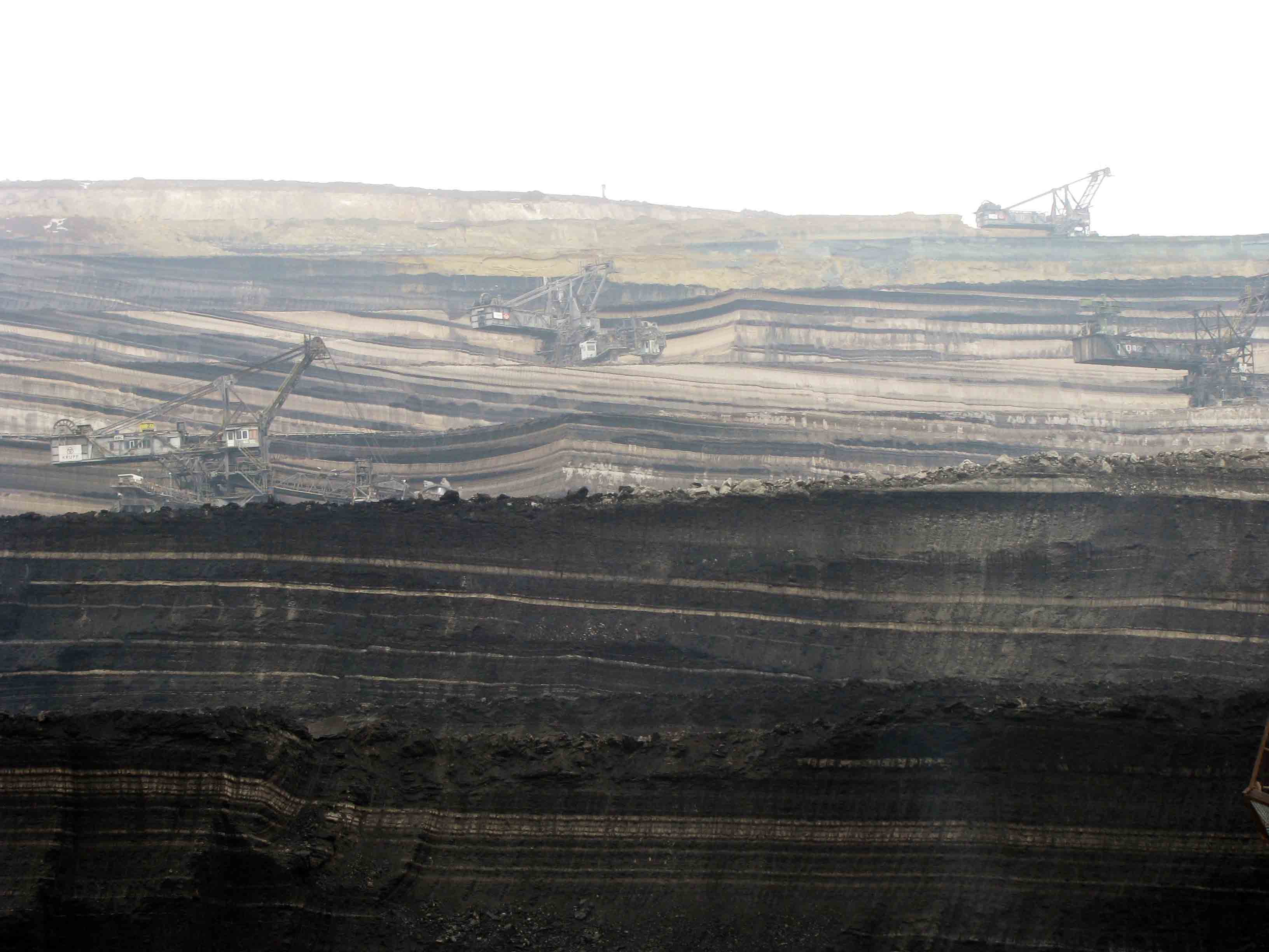
In the second picture a large excavation for a lignite mine is presented. The depth of excavation of this multi bench cut is around 135m. The excavation of this type needs to consider bench stability of slopes with heights of around 18m and also overall slope stability for highs above 135m. In the second case a large part of a possible failure surface could be in a stress field of around 1500-2000kPa or even more.

 Coal mine slopes

In the following figure the two types of cuts are compared and one can easily understand the significance of scale effects in the design of the different cuts.

Scale difference of coal mine and highway slopes

The scale of the mine excavation is such that even in one cross section, one has to consider besides the stress field, differing geology (pic 4), presence of faults, ground water locations and pore pressures etc. We will focus on the stress dependency at this point.

mine slopes

According to Stark et al, (2005) both fully softened and residual failure envelopes are stress dependent. In this work Stark et al provides an empirical graph regarding the stress dependency until 700kPa of normal stress for residual friction angle and 400kPa for fully softened friction angle.

Shear strength information for higher effective stresses >1MPa are not readily available. Furthermore execution of such tests in very high effective loads is not easy for most commercial laboratories. It may even be very difficult to execute ring shear tests in very high loads due to sample thickness and squeezing out from the sides.

In such high slopes the failure surface can pass from a number of soil layers with different shear strength properties. It is not easy to evaluate the “average” shear strength of layers involved in a possible failure surface. Unfortunately a rule of thumb for selecting shear strength parameters for such slopes cannot be provided. Engineering judgment is required in selecting such parameters and the stress conditions must not be ignored. Shear strength tests should be evaluated in relation to the expected stress field.

Slope failures, landslides and mines

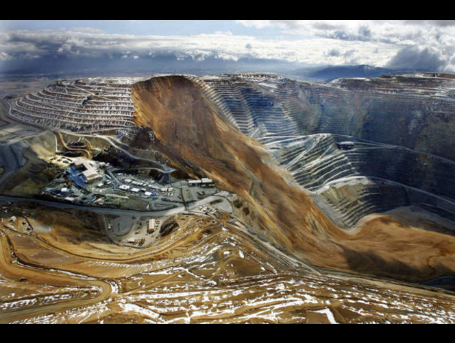
On 11 of April 2013, around 9:30 p.m. a large slide (maybe the largest) in the northeast section of the Kennecott mine occured (fig 1). The slide was preceded by slope movements that reached ~50mm per day. Two major questions could be raised, why this slide occurred and could it have been predicted before hand and remediated?

Kennecott mine

These are very difficult questions and require significant knowledge of the geology, geotechnical conditions of the area, operational practices, climatic conditions etc. In the following paragraphs some initial ideas regarding the stability of high mine slopes and some interesting references will be provided for interested individuals. The incident in Kennecott is an important lesson of how important continuous monitoring of slopes is in such mine operations.

I would like to start with a very interesting graph published by Hoek et al (2000), “Large-scale slope Design – A Review of the State of the Art”.

This chart presents slope height versus overall angle with solid markers representing unstable slopes and open markers represent stable slopes. This chart is for copper porphyry open pits. In this graph the Kennocott mine (Bingham Canyon) is also shown but not the April 2013 one.

It is very interesting to note that most of the unstable markers are located in a range between 35 and 45 degrees of slope angle. Although much information is required for detail evaluation of each point and why instability occurred, a trend can be seen. Can we assume that slopes designed bellow 32-35o would not provide stability problems?

In the next figure I would like to focus on scale effects when dealing with mine slopes in rock or even hard rock materials. In the down left side of the figure 2 a slope with 30 meters height is depicted. In the upper left one of 90m with the same spacing of joints and finaly on the right a slope of 500m again with the same spacing and trance length of discontinuities (figures adopted from Sjoberg, 1996).

What can be seen from this slope scale is that even solid lightly fractured hard rock can be seen as an accumulation of infinite rock items such as a gravel slope or sand slope, just with better interlocking. One additional question can be, “what is the effect of bridging (intact rock between discontinuities) in such large scale slopes”? Very difficult question but maybe the previous graph provides an explanation (maybe negligible?).

Is the scale effect, in relation to joint spacing, orientation and stress field producing a ductile (sand or gravel like) behavior that may control the overall stability?

In the left graph (Ross, 1949) tests on intact marble with different confining pressures are presented. On the right (Holtz, 1981) normalized stress – strain with different confining pressures for dense Sacramento sand are presented. As can be seen, both materials in low confining pressures present a brittle behavior and as confining pressure increases, the behavior becomes more ductile and strain hardening.

Strong rock and dense sand can have the same behavior in different stress scale? And if this is the case, should high slopes be treated in a different way? Neglecting cohesion and using a possible “critical state friction angle” approach in slope stability? This issue requires additional research and detailed case studies but at least we can have some perspective regarding to scale effects.

References:

Sjoberg J., (1996). Large scale slope stability in open pit mining – a review. Technical Report 1996:10T, Lulea University of Technology

Hoek E., Rippere K. H. and Stacey P.F. (2000). Chapter 1, Slope stability in surface mining, Hustrulid, McCarter, VanZyl (eds), Society for Mining, Metallurgy and Exploration

Ros Μ. und Eichinger Α. (1949). Die Bruchgefahr fester Korper (Eidgenoss. Material prufungs versuchsanstalt, Ind., Bauw. Gewerbe. ZUrich, l72), 246 pp.

Holtz R. D., Kovacs W. D., (1981). “An Introduction to Geotechnical Engineering”, Prentice Hall.

How long can stiff fissured clay slopes stand?

Coming back to the issue of stiff fissured clay slopes, one very important question is the standup time of a slope excavated or formed (natural erosion etc) with higher inclination than the one that would be the outcome using fully softened shear strength.

Skempton (1970) in his paper “First time slides in over consolidated clays”, provided a graph presenting the decay of strength with time to almost fully softened where failure of slopes in London clay occurred (pic 1).

Strength changes with time for London Clay (from Skempton, 1970)

Mesri et al (2003) in his paper provides a graph (pic 2) compiled from numerous case studies of failed slopes in stiff fissured clays in which the vertical axis presents the percent of failure surface length (Lr) in residual condition to the total observed failure surface length (Lt)  and on the horizontal axis the age when the slopes failed. The far left points are of unidentified time. Time to failure range from a couple of years to decades.

Ratio of slip surface segment assumed at residual condition to total slip surface length ploted against age of slope

VandenBerge et al (2013), mention that “The time required to reach fully softened strength might be as little as ten years in some cases, and as long as 60 years in others”.

Potts et al (1997) in the paper “Delayed collapse of cut slopes in stiff clay” presented complex coupled finite element analyses assuming strain softening soil behavior capable of swelling. The analysis requires among other parameters the coefficient of permeability which varies with depth, and coefficient of earth pressure at rest. With this complex parametric analysis they conclude that 3:1 (H:V) slopes produced failures between 11 and 45 years. And steeper slopes fail in less than a decade. 15m high slopes failed after 145 years. All these slopes produced deep seated progressive failure.

It is very interesting to note that they evaluated deep seated failures although the problem of investigation was recent shallow failures in highway cuts and embankments.

Another attempt from Kovacevic et al (2007) presented in the paper “Predicting the stand up time of temporary London Clay slopes at Terminal 5, Heathrow Airport” in which again a complex finite element analysis with swelling behavior and differing Ko was executed. The investigation was for both shallow and deep seated failure. The conclusion of the study was that shallow failures occurred earlier than deep seated and the time to failure was influenced most by the assumptions of permeability and the effect of suction.

Cuts in stiff fissured clays will stand up for an undetermined time before failure occurs when inclined steeper than fully softened strength requires. The time may be from six months to hundred or more years. Investigating the stand up time is very complex and requires sophisticated numerical analysis which also utilizes assumptions in many of the parameters used. Very important parameter is the permeability of the clay in the development of swelling and softening.

This is captured in the classical Terzaghi, Peck and Mesri, 1996 book in which it is stated that “If the surfaces of weakness subdivide the clay into fragments smaller than about 25mm, a slope may become unstable during construction or shortly thereafter. On the other hand, if the spacing of the joints is greater, failure may not occur until many years after the cut is made.”

In my opinion the spacing and orientation of joints is the controlling parameter of permeability in such materials. So highly fissured materials with very close spacing may develop shallow slope failures very quickly. More widely spaced  stiff fissured clays with fewer joint systems can provide significant delay time to failure.

A second important issue is the evaluation of shallow or deep seated failure and how a deep seated failure can be defined. This is something very important that will be covered in another entry.

Slope design in stiff fissured clays

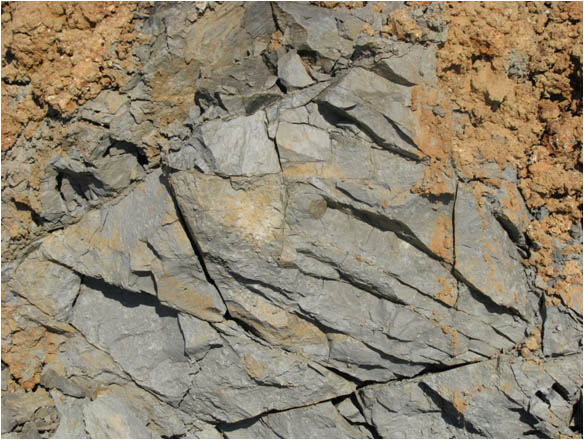
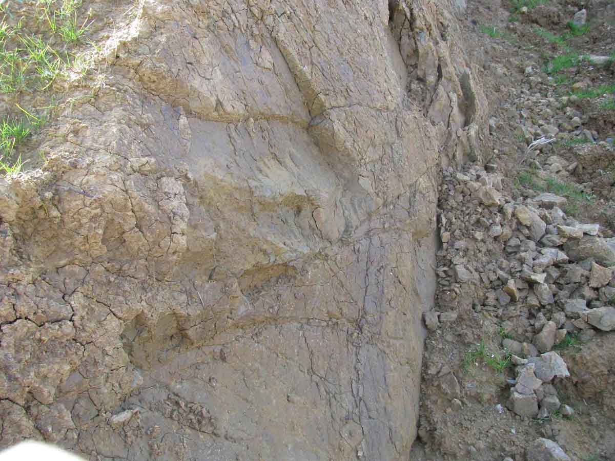
A very difficult issue is the design of slopes or cuts in stiff fissured clays (pic 1). The difficulty lies in the evaluation of shear strength for stability calculations. Much work has been done on this issue especially by Skempton (1964) with his excellent Forth Ranking Lecture titled: “Long-term stability of clay slopes” and many others have contributed significantly on this issue.stiff fissured clay

In the classical Terzaghi, Peck and Mesri, 1996 book the following is mentioned regarding this issue: “Almost every stiff clay is weakened by a network of hair cracks or slickensides.” (pic.2). “If the surfaces of weakness subdivide the clay into fragments smaller than about 25mm, a slope may become unstable during construction or shortly thereafter. On the other hand, if the spacing of the joints is greater, failure may not occur until many years after the cut is made.”Stiff fissured clay exposed next to a sliding soil mass

The reduction in strength with time, due to the presence of fissures, has been attributed to swelling and softening due to water infiltration in this hairline cracks especially when stress relaxation and crack opening occurs in excavated slopes.

Laboratory shear strength evaluation of such stiff fissured clays is difficult because large samples are required in order to include significant number of hairline cracks and even if such samples can be tested, the long term swelling and softening cannot be fully developed in the laboratory.

Duncan and Wright (2005) propose, based also on the work of Skempton (1970) to use the fully softened strength for long term slope stability evaluation of stiff fissured clays that have not undergone any prior movement or failure. This fully softened strength can be correlated to the peak strength of normally consolidated clays. In the laboratory the fully softened strength is evaluated on remolded samples of stiff fissured clays.

A very recent paper by VandenBerge, Duncan and Brandon, 2013 presents the outcome of a workshop that took place in 2011 at Virginia Tech, regarding the fully softened shear strength for stability of slopes in highly plastic clays.

In this paper the most recent views regarding the softening process, the way to measure or estimate the fully softened strength and how and when to use it in stability analysis are presented. Together with the paper of Vanderberge et al, it is worth reading the Lade paper in Engineering Geology (2010), titled “The mechanics of surficial failure in soil slopes” where a power function failure model is proposed for the shear strength of clay for shallow stability evaluation. This criterion is mentioned also in the paper by VandenBerge et al (2013).

I would like to bring attention on some issues which are mentioned also in the papers but relate more to practical issues of the subject:

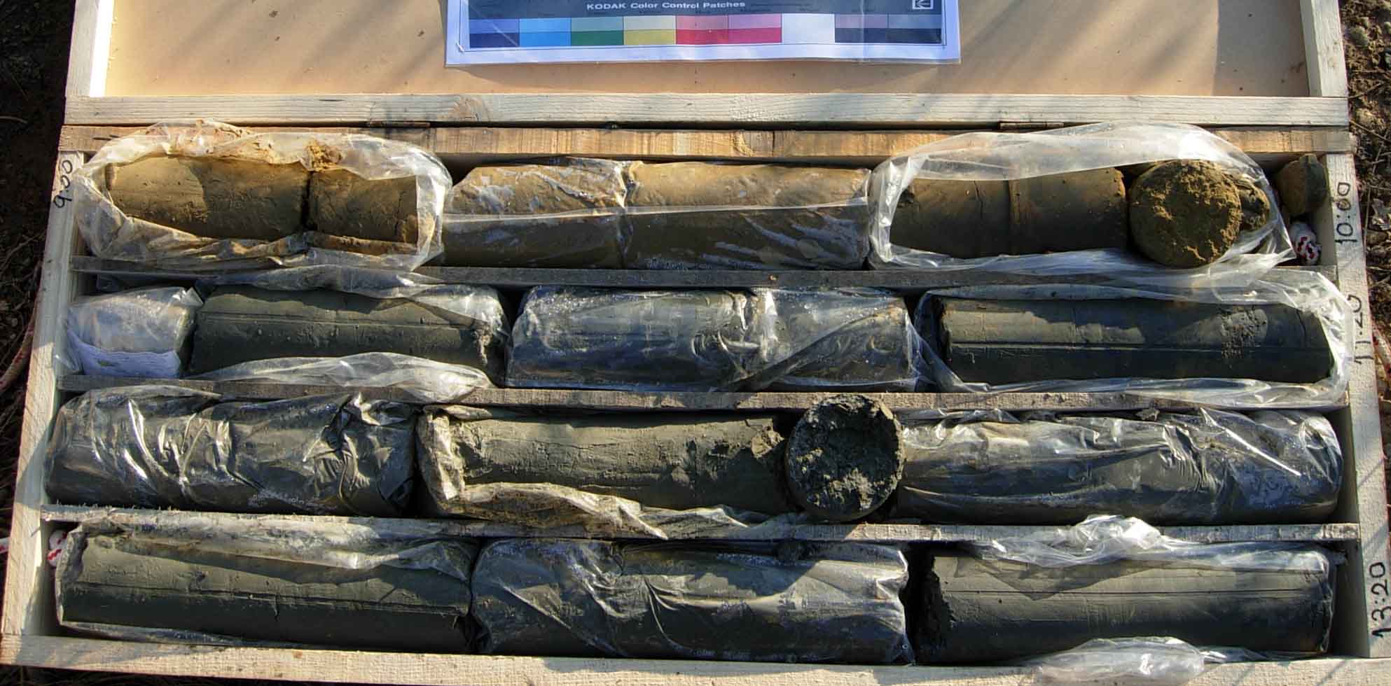
  1. Great care should be given when site investigation is executed and evaluated in such stiff fissured caly materialsFissured clay. If core samples are not collected then it is very difficult to distinguish between stiff clay and stiff fissured clay. Even when samples are collected, great care should be given to break up some core samples because the fissuring will not be observed as can be seen in the picture 3.
  2. In situ tests such as SPT will produce high values, misleading the investigator to think that a very strong (even cemented) material is found.
  3. Shear strength tests on intact samples will produce high values of cohesion, again misleading the investigator to believe that a very strong material is present. In the laboratory the fissuring may not be reported during sample preparation due to the small sizes required.
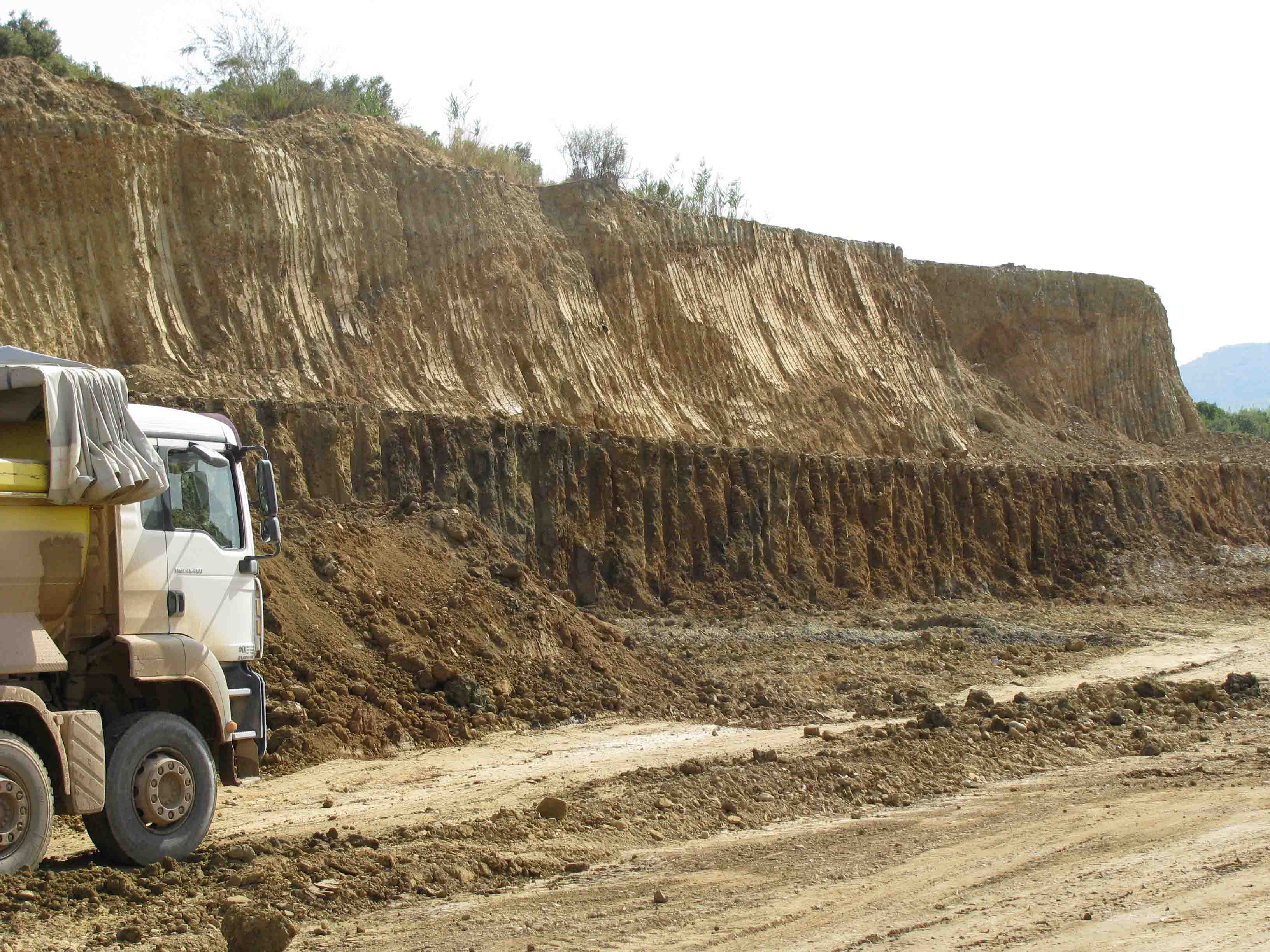
  4. The additional difficulty comes on how to persuade the Owner or Contractor about the problems (failures) that Steep stable excavation in stiff fissured clay  may be formed after the slope has been excavated (maybe after very long time). They will evaluate the data from the investigation which show high values and if they are not fully aware about the behavior of stiff fissured clays they will push for a more optimistic design in order to reduce excavation volumes. The situation becomes even more difficult in design – built projects where during excavation the contractor may need to use hydraulic hammers to break up the material and steep slopes are  stable (pic. 4). In such situation everybody “blames” the designer for a very conservative design if fully softened shear strength has been used.
  5. The evaluation of existing stable slopes not designed with fully softened shear strength is another difficult situation. If the fully softened shear strength is used the FS may be found to be even below unity FS<1.0 but the slope is stable for a couple of years after excavation. It is difficult to persuade the Owner of such slopes (usually highway or railway) that in the future stability problems may occur.
  6. Finally it is very difficult to evaluate in what part of the slope and how deep you will use fully softened values especially for high slopes.
  7. Another critical issue is the evaluation of the long term pore pressures to be used in the analysis. In my opinion this is the most difficult issue but I will get back on this in another entry because much could be said.

As a closing remark I would like to state the final conclusion of the Vanderberge et al, 2013 paper: “Consideration of local experience with regard to slope performance, recognition of the possible consequence of slope failures, and application of sound engineering judgment are all essential elements of a comprehensive approach to geotechnical engineering of slopes.”

Proper amount of geotechnical investigation

The situation is like this: A major problem occurs in a bridge abutment and significant differential settlement between abutment and road is observed. The Owner decides to investigate the situation and assigns the job to a joint collaboration between a University and a Geotechnical Consultancy Firm.

The collaboration requests the execution of three boreholes to a depth of 30m, execute a number of consolidation tests some in a private laboratory and some in the laboratory of the University, together with other appropriate soil tests such as gradation, shear strength etc.

The collaboration provides a report in which it is stated that the previous geotechnical investigation did not evaluate properly the soil conditions because only one (1) drilling of 20m depth was executed in the abutment and did not evaluate properly the thickness of a compressible clay layer. Also based on the 15 consolidation tests executed by the collaboration, the coefficient of consolidation and the preconsolidation pressure estimated by the previous Geotechnical Consultant were optimistic. The previous consultant had executed three (3) consolidation tests.

So the conclusion of the report was that the problem was due to the optimistic evaluation of settlements made by the previous Geotechnical Consultant which had executed only one (1) drilling of twenty (20) meters and limited consolidation testing.

It is very easy to come to a “correct” solution after a significant amount of geotechnical investigation (money spent) has been executed in an area where a problem has occurred. The problem is known, some geotechnical information is available and the investigation can be targeted appropriately.

But how easy is this to be done from the start of a project? Most people involved in geotechnical investigation know how difficult is to persuade the Owner, Contractor etc to execute even the minimum required investigation not to mention the increased difficulty to persuade for additional investigation in an area where a hint of geotechnical problem is speculated.

In the fast track way that most projects are executed these days how can the geotechnical investigation and design produce “accurate” results?

How can we persuade the Clients that less is not more in geotechnical investigation and design? Food for thought.

How difficult is to evaluate superficial landslides – mudflows?

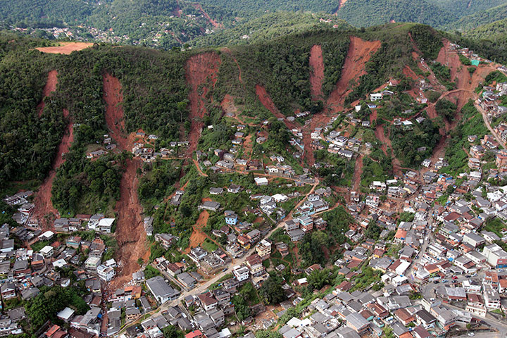
Reading on the news about the dramatic landslide-mudflows (picture) that occurred (again) in Petropolis near Rio de Janeiro, with significant fatalities, one thinks could this have been predicted and more so avert it?Brazil mudflow

Even in an area prone to superficial mudflows and thin landslides, it is very difficult to accurately predict the occurrence of such a landslide. This is for the following principal reasons:

  1. It is difficult to assess the geotechnical parameters of a superficial material that undergoes continuous drying and wetting cycles.
  2. The tests are usually performed in saturated samples and in higher effective stresses that are usually present in superficial slides.
  3. A linear Mohr – Coulomb failure criterion is used when it may be more appropriate to use a power function that defines a curved strength envelope with minimum or even zero effective cohesion in very low to zero confinement (especially for uncemented soils).
  4. The soil is usually unsaturated with some (or even large) suction which is modified during rainfall infiltration. The pore pressure regime is very difficult to assess without continuous specific monitoring.
  5. Numerical techniques that can accommodate such complex problems are not widely available and not everybody knows how to use efficiently such models.
  6. The usual triggering mechanism is intense rainfall which increases the pore pressures in the superficial soil.  Since the way water infiltrates in the unsaturated soil, depends mostly on permeability, water content at the time of rainfall, the vegetation cover and the angle of the slope, the problem of evaluating such pore pressures becomes even more difficult.

This problem of predicting mudflows is usually assessed based on prior experience and some statistical evaluation of past mudflows and amount and intensity of rainfall. Can we do better?

SPT field testing

Today I came across a very interesting paper regarding site investigation with SPT and CPT. In this paper written by J. D. Rogers, the historical development of SPT from its creation from Charles R. Gow, to its modification and standardization by K. Terzaghi and A. Casagrande and its standardized use today are presented.

The road to SPT corrections and the reasoning behind them is provided while a critical evaluation of these corrections is presented. Some pitfalls in the execution and evaluation of the results can be found in this paper. Practitioners will find it to be a good review regarding SPT and new geotechnical engineers can understand the limitations of the methods.

Some issues that are not covered in detail regarding SPT testing and in my opinion are very important are the operator’s (driller) proficiency and the appropriate supervise. This is of paramount importance and I would like to share some insight.

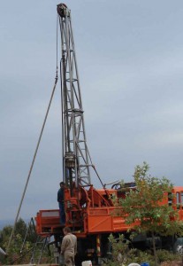
I was present at an SPT execution in a hot summer day around 2:00 pm, the test had started while the geologist in charge and I were evaluating some outcrop geology not too far from the drill. As we started approaching the drill (the driller could not see as yet) I observed a very lazy move in the way the rope was tightened in the rotating drum.

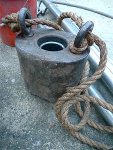
The SPT hammer (a safety donut type, picture 2) was not traveling the appropriate height before it was released for its free fall. Even when it was released the driller was somehow holding very loosely the rope so the energy of impact was even more reduced. As it is easily understood the SPT blow count would be significantly higher than that required for the specific conditions if the test was executed correctly.

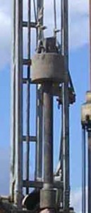
Another time I observed a driller (probably wanted to impress his supervisor) executing the test in a very quick pace. During this quick pace he was lifting the donut hammer and not releasing it as quickly needed for that pace. The safety donut was hitting the rod in the upper end (picture 3), displacing it upwards from the ground. It is easily understood that SPT blow counts again would not be correct.

Automated SPT execution equipment are available that could eliminate these issues but they are not a standard practice due to cost and other operational issues. Even if such equipment were used, other problems could arise during SPT execution.

It is very important to understand that SPT values are numbers with high scatter, even for very homogeneous materials, when evaluating ground properties, great care and judgment must be executed. Corrections can be found and applied but human errors are not so easy to predict or account for.